Translated with www.DeepL.com/Translator (free version)
The Cause
In 2007, Apple launched the first generation of iPhone, which completely changed people's understanding and awareness of smartphones, and smartphones and post-PC products have been strengthened, replacing what PCs could only do. The Kindle is not only designed to be used for reading books, but also has a hardware screen that can only be used for reading books: a black and white EPD screen. This screen can only display black and white colors (or gray scale), the response speed is also very slow (about 400ms-1s), and also can not actively light, must use ambient light to display... However, this screen also has some very important advantages, such as the display effect is very close to the paper, not harsh, only in the refresh power consumption and so on. A few years later, domestic manufacturers have also entered this field, the price of such electric paper books using the EPD screen to less than a thousand dollars. At that time I bought one, was really attracted to the effect of this display. At that time I thought if I could drive up with a microcontroller to play a good game. But at that time, their own poor technology, the screen is also expensive, did not successfully implement. Recently, I found that the price of large size (6 inches, model ED060SC4) E-Ink screen has been reduced to less than 50, so I decided to start researching its driver, and also to make the simplest application: desk calendar.
Preliminary research
First of all, for your convenience, let's distinguish a few terms, first is EPD, EPD is not the abbreviation of E-Paper Display, but should be the abbreviation of Electrophoretic Display, E-Ink is the registered trademark of PVI, used to refer to their EPD products. However, PVI is not the only company that produces electronic paper, TMC, Lundin, AUO, Jiaxian and LG are all producing similar and compatible EPD products, so it is better to call them EPD rather than E-Ink. TFT LCD and so on, such as the HR-TFT LCD used by Pebble is also advertised as electronic paper, but actually not EPD.
In fact, in March last year, "Radio" has published an article on the small size EPD driver, at that time read the feeling is quite simple, is the same as driving the general serial LCD, through the SPI interface to send instructions and data to the EPD controller can be. But after a closer look, I found that for large-sized screens is not the case at all. Such large size EPD panels usually do not have integrated controllers! And the general practice is in an application outside the controller through the bus to expand a separate EPD control IC to complete the control of it, usually using PVI or EPSON controller. This kind of controller is expensive, but also the use of BGA package, the controller itself also need to expand the SDRAM or DDR SDRAM to use, quite troublesome, so few individual enthusiasts to try to drive this screen. However, what details are hidden in this expensive and complex controller? Let's start with the driving principle of EPD.
First, the electrophoretic display, simply put, is the movement of charged particles in the electric field. There are two main types of specific implementation, the first is to allow titanium dioxide particles dispersed in hydrocarbon oil to achieve the technology, this technology is the simplest in principle, but the short life and difficult to process, and therefore did not successfully commercialized. Nowadays, another technology called microencapsulation is common. This technology was proposed by a few MIT undergraduates in the 1990s, and E-Ink was formed in 1997 to commercialize the technology, and continued to be developed in collaboration with Phillips two years later, before being sold by Phillips to PVI in 2005. between the electrodes instead of dispersing the particles directly between the electrodes as in the previous technology. Subsequently, a matrix of electrodes is arranged on the front and back of the particles, and then the electrodes are energized to attract the particles and change the color of the capsule surface, so that the electrodes are crossed to form a pixel for the image display. The current practice in production is to use the same TFT technology as in existing TFT LCDs to improve the contrast of the multiplex driver, and to arrange the electrodes only on the bottom of the capsule.
The simple principle is this, to put it bluntly, is to energize and change the pixel state, but this is actually known without speaking, so there is no substantial progress. However, I did find a Dalian Jiaxian company's public driving documents (in fact, the 2-inch SPI EPD screen is also developed by this company), the document describes the direct use of a microcontroller to drive the controller-free electronic paper screen method.
First of all, as LCD screen, EPD screen is also driven by scanning, scanning is divided into Gate driver and Source driver, that is, row and column driver, the structure is as follows.
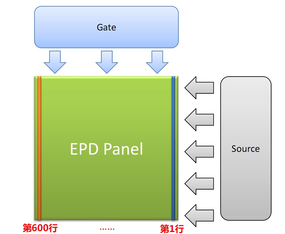
The driver is of course integrated in the panel in COG way, and the controller only needs to send scan signals to the driver in a certain timing sequence. The pixel data is moved into the Source driver through the data bus, and after latching, Gate opens this line for driving, while continuing to move into the next line of data, and after latching, Gate opens the next line for driving, thus completing 600 lines of scanning line by line, for 1 frame. The LCD drive without controller is like this, maintaining a certain frame rate to keep refreshing to get a clear image. So, the difference with the LCD comes, unlike the LCD where each pixel just sends the display data (for black and white LCDs it is 0 or 1 for light or dark, for color LCDs it sends RGB data directly), the EPD sends "operations" for each pixel. Each pixel has 3 types of operations, namely, no drive, drive black and drive white. Therefore, each pixel takes 2 bits when sending data, but remember, 2 bits per pixel does not mean 2bpp color depth, but multiple operations are possible. In addition, EPD requires multiple frames to be stacked to complete the display because of its slow response time. This is why it is called "drive black" and "drive white" instead of "black" and "white" directly. This is why they were called "drive black" and "drive white" instead of "black" and "white". To determine the data to be sent in each frame, there is a waveform table to determine the data to be sent in a particular frame based on the previous pixel data and the new pixel data: !
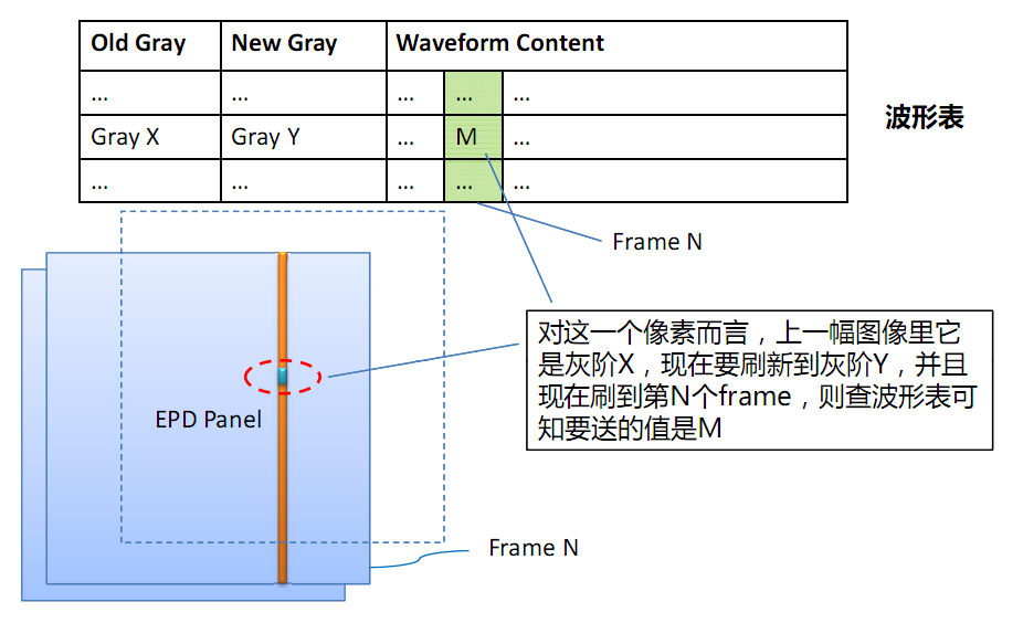
There are also some considerations listed in the manual. As you can see in the figure above, the EPD needs to know both the data of the previous frame and the current data to be displayed for a total of two frames when refreshing in order to complete the table lookup to display the data, so it needs enough RAM to cache at least two frames of content. In addition, a frame time of 85ms or less is required for grayscale display, and different frame times require different waveforms. It is also warned not to connect the EDP screen with a long frame duration, which may cause damage.
Thus, the main point of a dedicated EPD controller is the timing of the driver and the waveform table. However, how to solve this waveform problem? I initially thought of the reverse, but later proved completely unnecessary.
In addition, you can find a foreigner on the Internet to do the EPD driver experiments, using the same ED060SC4 screen, and he used a worse processor (STM32L1), in order to solve the problem of RAM is not enough to use the block refresh, but only to achieve a single black and white display (no gray scale).
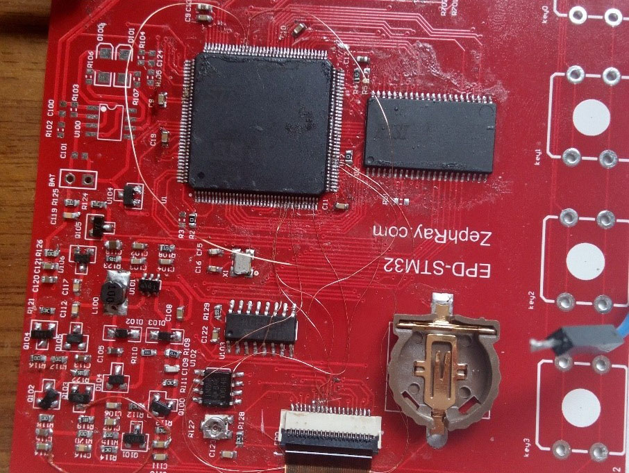
Circuit design
Not much fun, slightly.
Basic verification
The first thing I did was to solder the board to verify it. I first soldered the high-voltage part to test whether the voltage boost was normal, and found that there were several double diodes and transistors in the schematic diagram that were drawn backwards, and after turning over the soldering solution, the required voltage was output normally, so I could start writing the program.
The program is just to achieve the Gate and Source drive timing, first of all, or look at the timing diagram given in the manual: !
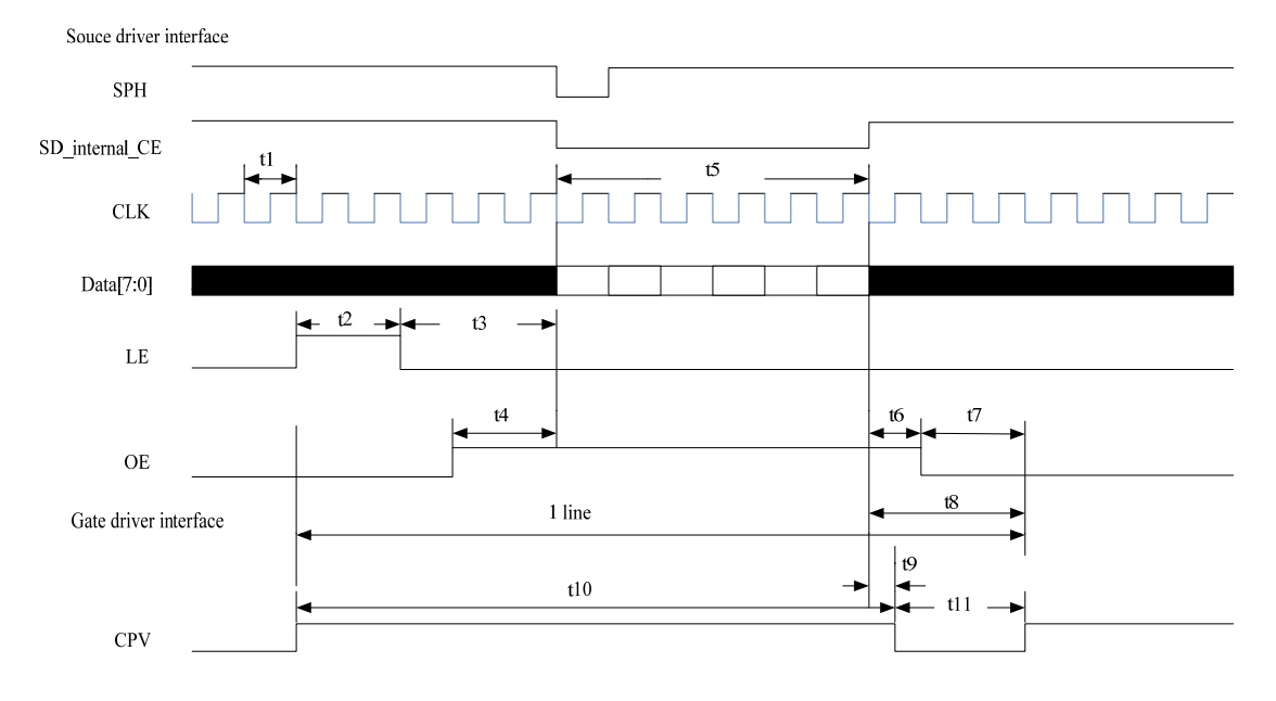
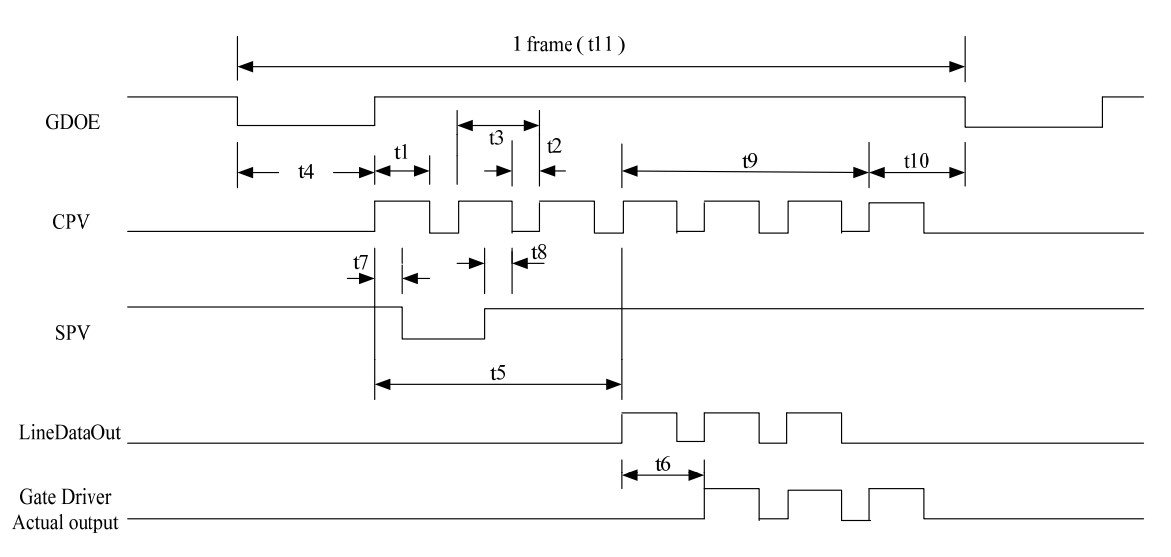
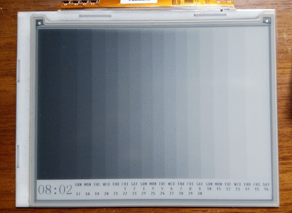
The previous picture is Source timing while the next one is Gate timing, note the relationship between the corresponding two, the following is the written code, note that the screen may have individual differences, it is recommended to test with 0xAA (white) and 0x55 (black) first, incorrect timing may lead to some strange effects (such as can only brush white can not brush black, can only brush lines can not correctly trace the point, etc.).
void EPD_Vclock (void)
{
  unsigned char i;

  for (i=0;i<2;i++)
  {
    EPD_CKV_L();
    DelayCycle(20);
    EPD_CKV_H();
    DelayCycle(20);
  }
}

inline void EPD_Hclock(void)
{
  EPD_CL_H();
  EPD_CL_L();
}

void EPD_Start_Scan(void)
{
  EPD_SPV_H();
  EPD_Vclock ();
  EPD_SPV_L();
  EPD_Vclock ();
  EPD_SPV_H();
  EPD_Vclock ();
}

void EPD_Send_Row_Data(u8 *pArray)
{
  unsigned char i;
  unsigned short a;

  a = GPIOC->IDR & 0xFF00;

  EPD_LE_H();
  EPD_Hclock();
  EPD_Hclock();

  EPD_LE_L();
  EPD_Hclock();
  EPD_Hclock();

  EPD_OE_H();

  EPD_SPH_L();

  for (i=0;i<200;i++)
  {
    GPIOC->ODR = a|pArray[i];
    EPD_Hclock();
  }

  EPD_SPH_H();

  EPD_Hclock();
  EPD_Hclock();

  EPD_CKV_L();
  EPD_OE_L();

  EPD_Hclock();
  EPD_Hclock();

  EPD_CKV_H();
}

void EPD_Frame(void)
{
  unsigned short line,frame;

  for(frame=0; frame<FRAME_INIT_LEN; frame++)
  {
    EPD_Start_Scan();
    for(line=0; line<600; line++)
    {
      EPD_Send_Row_Data( EPD_Buf + line*200 );
    }
    EPD_Send_Row_Data( EPD_Buf );
  }
}
I would recommended to start with some image on the EPD, then test on the board to see if it could display black or white.
Display greyscale
The EPD screen is called E-paper because once it is finished "printing", it will retain the content even if the power is disconnected. So as you can imagine, when we actually driving the EPD screens, we have three different operations: write (encoded 0b01), wipe (encoded 0b10), leave it as is (encoded 0b00). The first operation will turn a white pixel into black, the second will turn a black pixel into white and the third will do nothing. More about these operations later. But there is a big drawback of EPD displays, that is the EPD pixel need some time to turn itself from black to white or from white to black. And that time is usually more than 300ms so we say EPD have a long response time.
However, the EPD is usually refreshed at a higher frame rate, like 60Hz. So you can see under 60Hz setting, the pixel won't be able to fully turn around in one frame. So there are two ways, one if lower down the refresh rate, aka keeping one frame longer, another is adding more frames. For an example, if your screen have a response time of 1/3s(333ms), you can either lower the frame rate to 3Hz or send 20 same frames under 60Hz. My driver used the later method. The reason is that when using the first method, you can actually see the screen refreshed up to down since the data is being sent in that speed. The second method (more frames) would not have this effect. You see the whole screen get refreshed together. (though actually still up to down but you can't see) So here it the full idea: assume we start from a white screen which have a resolution of 2px 1px, and we want it to display something like, one light pixel followed by a dark one: [ ]. So for the first pixel, it's already white (we start from white), so send the third operation (leave it as is) to the screen. For the second pixel, it need to be black, so we send the first operation (write) to the screen. And that’s one frame, we are running under 60Hz, so send 20 times. And we should get would we hoped.
But what if you stop driving a pixel before it totally turned around? Like, we send only 10 frames in the last example. The answer is that it would stay gray. And that's the fundamental of grayscale display on EPD panels. By controlling the driving time, we can create 4 shades or even 16 shades of gray. My driver used 4bpp(16shades) mode for better image quality, but if you can understand the principle, you can easily modify it to 4 shades or maybe 32 shades. Okay here is the thing. In 4bpp mode, there are 16 shades of gray. Let's continue with the assumption we made about the response time, 1/3s and begin with a white screen. If we evenly divide 1/3s into 15 slices, which is 1/45s each. So then we turn the frame rate to 45Hz, so one frame is 1/45s. For the pixel that's black, it’s obvious we want to send “write” command to the screen for 15frames, and it would turn black. For the pixel that’s white, just send “leave as is” in all 16 frames, it would leave white. That’s essentially the same as before. But if we want it to be the first shade of gray (which is, 1/15 of the brightness, note that 15/15 is black and 0/15 is white), simply send “write” in the first frame and “leave as is” in all other frames. So, the fourth shade of gray would be 4 frames of “write” plus 11 frames of “leave as is”. So what if we want 32 shades of gray? Adjust the frame rate to 93Hz and we are almost ready to go.
Unfortunately, things are not that easy. First of all, our STM32 software driving method is unable to achieve a refresh rate of 60Hz. Actually it can do only about 12Hz. So 4 frames is enough to drive the pixel from black to white or from white to black. It would be fine if I stick with monochrome mode or 2bpp (4-level) grayscale mode. But what if I want to do 4bpp mode, I have to use some tricks. Normally, the MCU send the data to source driver of the screen, when finished sending, it let the source driver latch the data and actually drive the pixels. In the meanwhile, the MCU started sending the data of next line. When finished, the MCU latch the data and tell the gate driver to switch to the next line. So the line driving time is roughly the time of the process of data sending. Now the data sends too slow due to the slow CPU/GPIO, so it set a lower limit of driving time for me. But as I have said before, more grayscales need higher frame rate, which actually means lower driving time per frame. In the normal way, the driving time is roughly the reciprocal of frame rate. But by using a trick, we can break this relationship, make driving time much lower than the reciprocal of frame rate. It’s actually easy. When MCU finished send one line, it would latch the data, and wait for a short period t1 of time, then turn off the source driver. So when actually sending the data, the source driver is off, the actual driving time is that t1. This method would make the frame rate even lower and make it slower to display a image since the time when MCU is sending the data is “wasted”. But it turned out to be a great workaround for me since I don’t often refresh the screen.
The second problem is that the brightness vs time is not linear. For example, 7/45s of driving time is supposed to give us a brightness of 7/15, but actually maybe 1/2, there is a little offset. Well, offset is generally okay but the real problem is that some times some shades get too close to distinguish. Thus, many details are lost. Believe or not, it’s even easier to resolve this using the workaround I mentioned before than using the normal way. I simply added a look up table of t1, so different frames can even have different driving times! The result turns out to be great.
Function implementation
In fact, once the screen driver is completed, the rest of these features are simple issues to implement, nothing new, compare the clock class is something that most enthusiasts do to get started, right? Hardware on the design of a DS3231 RTC chip, did not use the STM32 built-in RTC is to improve stability and accuracy, in any case, timing or its job.
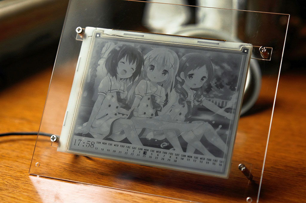
First of all, the functional design, my current design, the entire screen is divided into two parts, the upper 530 lines for the display of a static picture, the next 70 lines for the display of the time and the month's calendar, the picture is stored in the SD card, automatically replace a daily. Of course, some people may feel that this puts the cart before the horse and the time should be put on the top to show a large right, but this is all secondary, after all, these codes are very easy to modify, I write this article's main purpose is not to do a perpetual calendar but to share the controller-free EPD electronic paper drive method, the calendar is just an application demonstration.
Here by the way insert a little knowledge about the refresh mode of the EPD. In fact, if you have used Kindle or other e-book reader, you should know that this screen has two refresh modes, one is called all refresh, one is called partial refresh. The most intuitive difference between the two refresh modes is that all the screen needs to be refreshed, while the partial refresh screen will leave a residual image. In fact, I personally think that this is not quite appropriate, but here or use this statement. In addition, because the EPD does not support the operation of the pixels when scanning, so you can also achieve a block refresh, that is, only a part of the operation and does not affect other areas. Here I am limited by RAM capacity and processor speed, and I can't support partial refresh, so all refreshes are full refreshes. But the use of chunk refresh, that is, the upper half of the screen and the lower half of the screen is refreshed separately, so as to avoid the display time when the entire screen to flash. But in fact, the whole refresh is divided into two types in my implementation here, one is the known refresh of the previous state, and one is the unknown. The known case is to brush from the original grayscale to black first (for example, the original is white to drive 3 frames to black, the second level of grayscale to drive 2 frames to black so, in fact, the number of frames to do some fine-tuning), and then brush to white to complete the clearing operation, while the unknown case is to brush 4 frames to completely black, and then 4 frames to completely white, so repeat two to four rounds to complete the clearing. In actual effect, the unknown state is much slower than the known state.
In addition, the response speed of EPD screen in different grayscale modes is not quite the same, the response time is about 300ms in pure black and white mode, 600ms in 4 levels of grayscale, and 1s in 16 levels of grayscale, I use 16 levels of grayscale for the picture part, and can only perform the slow full brush of the original situation, and 4 levels of grayscale for the calendar part. The calendar part uses 4 levels of grayscale to perform a fast full brush of the known original situation.
The code will not be posted, go to GitHub to find it yourself.
Result
Conclusion
This time I implemented controller-less EPD screen driving on the STM32, achieved greyscale display with limited data rate, and finished a demo with some basic functionalities. Kind of like a long time dream comes true. The schematics, source code could be found on my GitHub. Special thanks to @ntzyz for the help and contribution.