Note: translated using DeepL translator
DBI LCD
You should have seen on Taobao Raspberry Pi use small (between 2.4-3.5 inches) TFT board, it needs to be plugged into the GPIO interface to use. If you have played a microcontroller, you should know this type of liquid crystal, they are usually bus interface (DBI, Display Bus Interface), specifically i80 parallel bus, 68k parallel bus, i2c serial bus and spi serial bus these kinds of. Among them, 68k parallel bus and i2c serial bus are mostly seen in black and white screens. This type of bus interface screen is usually used with a microcontroller, because they are simple interface, can be achieved with GPIO simulation can also be achieved by a simple controller. At the same time, this type of screen built-in graphics RAM, you can scan the screen operation, but also to reduce the load on the microcontroller processor. Generally seen in low resolution (less than 480 × 320) LCD below 4 inches.
The previous mentioned scanning operation may be some people do not quite understand, I am here to specify the following, do not want to understand or can not read this paragraph can be skipped. First of all, the LCD screen pixel connection is also like the LED dot matrix in accordance with the row to the matrix arrangement, each row and column are only one lead. Then, when a line is connected, by controlling the level of different columns in this line, you can control the content of this line to display. The complete image can be displayed by constantly scanning different rows using the trailing shadow of the liquid crystal and the visual holdover of the human eye. This results in the screen having to be refreshed all the time in order to display the image. But the nature of LCDs causes them to be much more complicated to refresh than LEDs. First of all, the LCD pixels are not single conductor like LEDs, but the potential difference between the upper and lower polar plates will cause the LCD molecules to deflect, and it looks like the pixels are lit or off, so a simple scanning scheme like LEDs will cause many pixels that should not be turned on to be turned on. Another point is that the liquid crystal must periodically change the driving polarity, otherwise it will be polarized, resulting in the display content will gradually disappear. But in fact, we do not have to care too much about these details, we just need to know that the LCD is required to scan it.
Based on the above introduction, DBI interface LCD is a kind of LCD suitable for small devices such as microcontrollers, generally MP3, MP4 and early feature phones use this kind of LCD. Since the Raspberry Pi has GPIO, it can naturally use this kind of liquid crystal. As the Raspberry Pi is with hardware SPI controller, the frequency can reach a horrible 250Mbps, on the other hand, so the general use of SPI interface DBI of the liquid crystal.
Due to the simple interface, this type of LCD can usually be homemade adapter board, the price is very cheap. I use is Taobao on a certain 2.4-inch TFT about 20 yuan + enameled wire homemade LCD board. But this type of liquid crystal can not plug and play, and now talk about the use of methods.
How to use
When the Raspberry Pi was just released I tried to connect the DBI LCD on the Raspberry Pi, at that time it was quite a problem. First of all, you have to write your own LCD driver using the spi port transmission, registered as a framebuffer device in linux, you need to recompile the Raspberry Pi Linux kernel integration into it, there was no fbcp screen copy software, in order to let the main display mapped to the LCD, you need to disable the HDMI driver in the kernel compilation options or modify the In order to map the main display to the LCD, the HDMI driver needs to be disabled or modified in the kernel compilation options. fb order, and this is not hardware-accelerated, the playback of video on the LCD relies on software decoding, and can not play 3D games. But now it is convenient, someone wrote a driver called fbtft is to do this, and the compatibility is very strong, the default can be compatible with dozens of LCD control chips, and this driver is integrated into the official system of the Raspberry Pi, as long as the simple configuration can be enabled. The following I talk about the use of the method.
First of all, the hardware connection, if you buy ready-made Raspberry Pi screen module compared to the seller will also provide a tutorial on the use of it, I am here to talk about the connection for the general microcontroller screen module (I use my own single screen without a backplane, but also similar). First confirm that the interface is SPI, and then figure out the screen driver IC (can be found in the module's manual or screen manual), for example, mine is ILI9325. Next check the list of screens supported by default by fbtft: https://github.com/notro/fbtft/blob/master/fbtft_device.c, search for 9325 in there and you should see the following snippet.
.name = "itdb28_spi",
.spi = &(struct spi_board_info) {
.modalias = "fb_ili9325",
.max_speed_hz = 32000000,
.mode = SPI_MODE_0,
.platform_data = &(struct fbtft_platform_data) {
    .display = {
        .buswidth = 8,
        .backlight = 1,
    },
    .bgr = true,
    .gpios = (const struct fbtft_gpio []) {
        { "reset", 25 },
        { "dc", 24 },
        {},
    },
}
There are 3 9325 devices, the first one uses LoSSI (SPI Mode 3) interface, the second one uses 8-bit serial, the third uses normal SPI. Mine should be the third one. Note that while fbtft supports 8-bit parallel, but as it's implemented as CPU bitbanging, it would use lot of CPU time, so that's not recommended.
Connect DC and RESET to 24 and 25 respectively, and connect SPI to the Raspberry Pi's SPI.
Enable SPI in raspi-config and reboot. Enter sudo modprobe fbtft_device name=itdb28_spi, if the screen is full black then that's sucessful. To map the terminal to the screen, try con2fbmap 1 1. If the orientation is wrong, orientation=xx could be added to the modprobe, and things like speed=48000000 and fps=25 could also be used. Note the fps couldn't be too high.
To load the driver automatically at bootup, add spi-bcm2835 and fbtft_device to /etc/modules-load.d/fbtft.conf. Then add options like options fbtft_device name=itdb28_spi into /etc/modprobe.d/fbtft.conf.
To map the HDMI display content to the screen:
sudo apt-get install cmake
git clone https://github.com/tasanakorn/rpi-fbcp
cd rpi-fbcp/
mkdir build
cd build/
cmake ..
make
sudo install fbcp /usr/local/bin/fbcp
Then use fbcp to start mirroring.
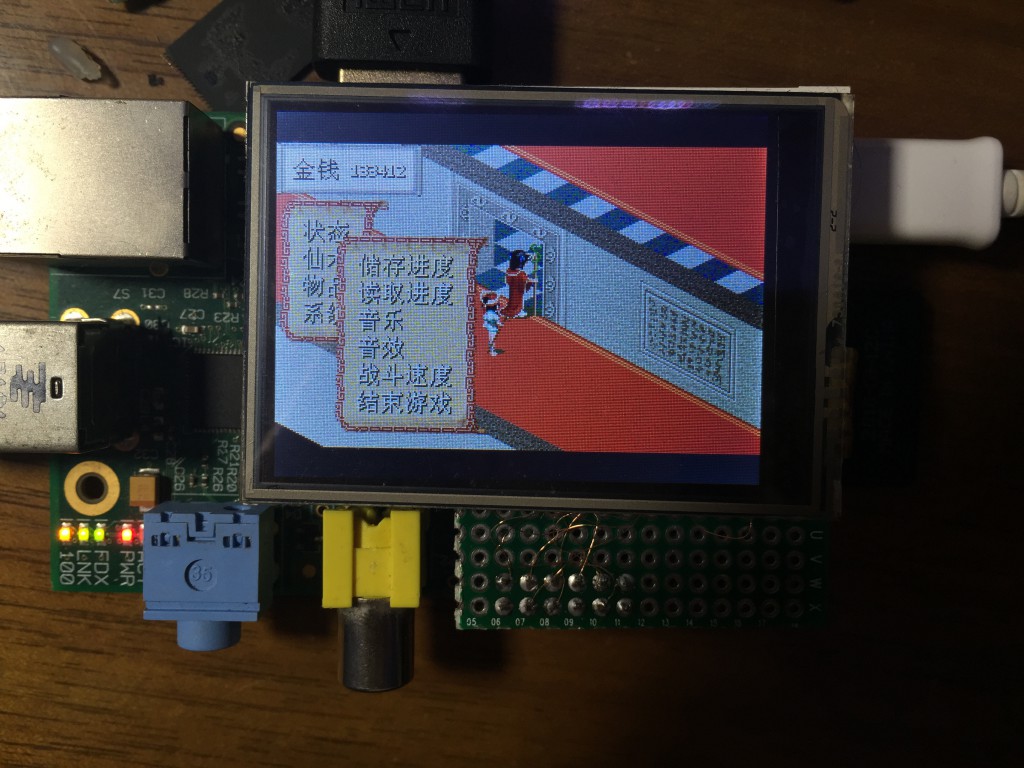
Results
Other Issues
The fbcp takes about 10ms to copy the screen, so there are 10ms latency. fbcp and fbtft works asynchronously, causing more latency and tearing. By looking at the image, there is an obvious diagnal tearing:
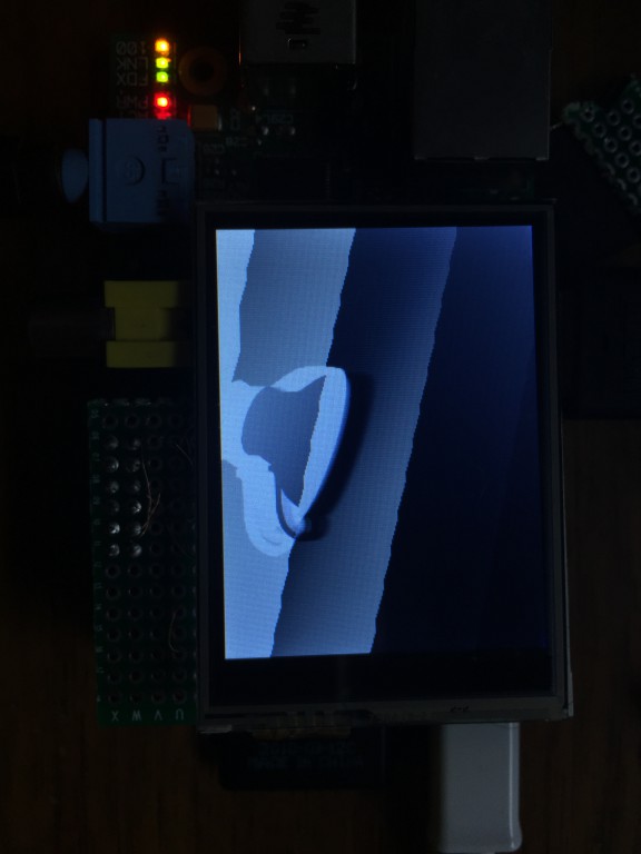
This is due to the screen itself refreshing vertically, but the data were written into the screen horizontally.