Introduction
The MIPI-DSI interface is widely used on cell phones and smart watch screens because it requires fewer IOs thus can provide some advantages in terms of connector size and routing difficulty. Obviously, as a screen enthusiast, I can't ignore this common screen interface. But I haven't had the chance to study it myself, so I took the opportunity of VerilogBoy to understand it in general. Given that MIPI is a proprietary interface, there are not many detailed descriptions of it on the Internet. This post is more or less just sharing my understanding of the MIPI DSI. This article is intended as an introductory reference for engineers or amateurs who need to debug MIPI screens.
Basic Concepts
What is important to know is that MIPI DSI is still just an interface for connecting screens, not for connecting monitors. Common examples of the former are DBI (including 8/16-bit parallel port and SPI), DPI (also known as TTL, RGB and PixelBus, etc.) and LVDS (also known as FlatLink), while common examples of the latter are VGA, DVI, HDMI and DP. The characteristic of the former is that usually the software driver contains screen specific parameters (like timing and voltage) and different screens require different drivers (or different parameters for the same driver). For the latter, the driver is usually generic and the display can transmit relevant parameters (e.g. EDID) to the driver via DDC/CI or other means, and the driver generates the required signals based on the information obtained. Generally speaking, the former is mostly used in embedded scenarios. However, note that eDP is a monitor interface that targets embedded usecase, which competes with DSI. This article only discusses DSI. The DSI is mostly just the definition of the physical layer and transmission layer, the screen operation is mostly same as the DBI and DPI. Or in some ways, DSI is kind of DBI and DPI packed up, so they can share a few pairs of differential lines together for transmission. All of the following discussion considers only one-way transmission from the host to the screen.
Low-power mode vs. high-speed mode
There are two modes of physical layer transmission for DSI, a low-power single-ended (LP) mode at 1.2V CMOS level, and a high-speed differential (HS) mode. In single-ended mode, the clock lines are not used, D0+ and D0- are used to transfer data and clock at a maximum speed of 10Mbps, and the other data lines are not used. In differential mode, the clock line is used to transmit the differential clock, and up to four pairs of data lines can be used to transmit data at a maximum speed of 1Gbps per pair of data lines.
By default, both data lines and clock lines are in LP mode (CLK+/CLK- are both high) after the screen is powered up. The clock lines in LP mode can enter HS mode using the following sequence:
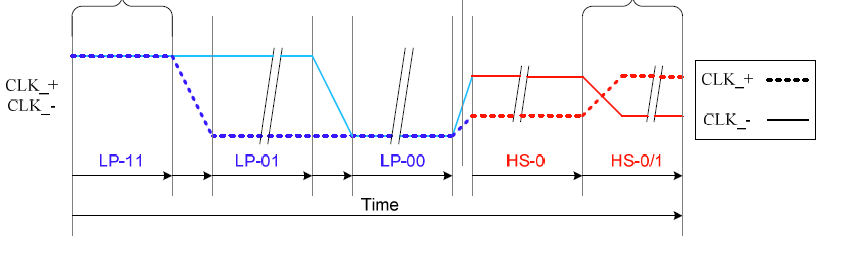
Pull CLK+ low first, then pull low CLK-, wait for a while and start HS transmission. Data lines could use the similar sequence to enter HS mode:
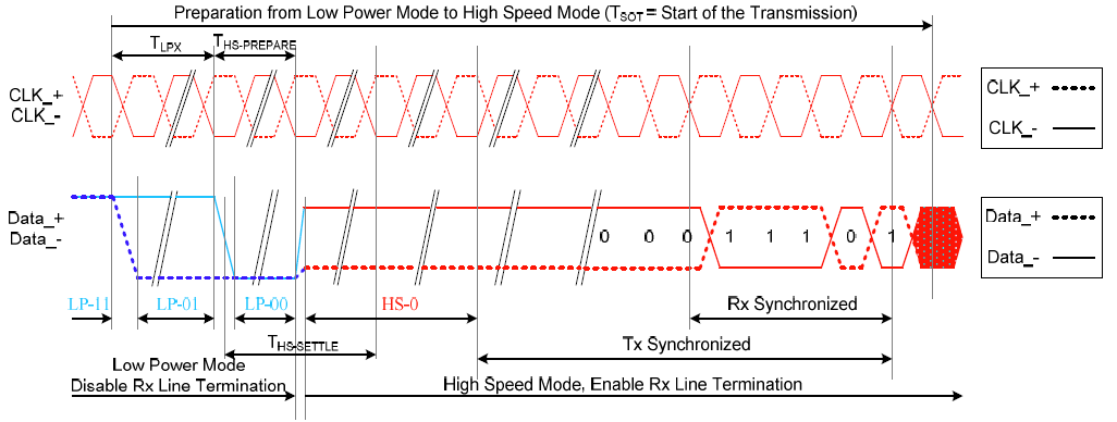
Compared to the clock lines, data lines has additional synchronization process. Before data transmission, the 00011101 sequence needs to be sent. Once synchronized, the data must be sent continuously. Otherwise it needs to return back to LP mode.
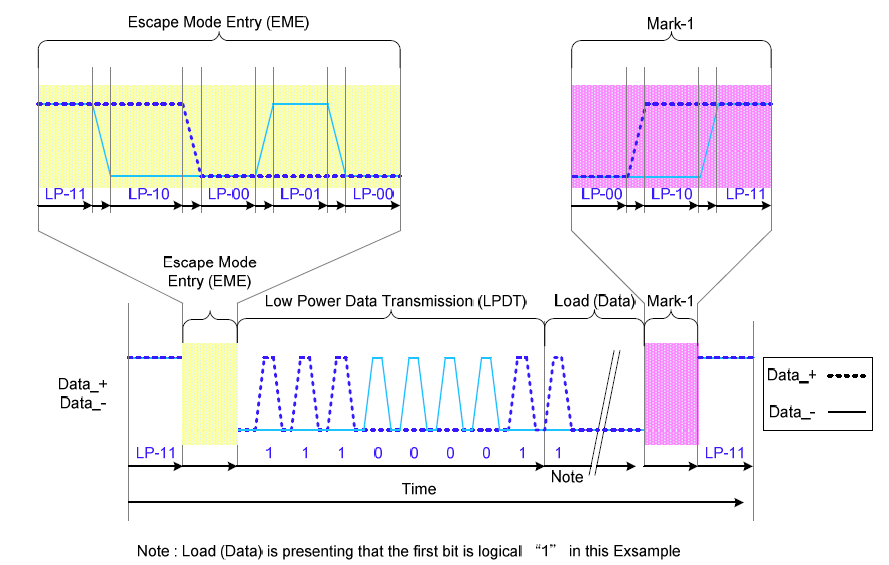
It's also possible to transfer data in LP mode, by using the LPDT (LP Data Transmission) in the escape mode. Note only data lines are shown here, as LPDT doesn't use clock lines. Typically clock lines stay at LP-11 (both clock lines at 1.2V). The clock could be derived by doing D+ | D- (OR).
Data packet
In DSI, the minimal possible unit for transfer is data packet. Packet could be transferred either in HS mode and LP mode. The packet content is the same regardless of the mode. In HS mode, multiple packets could be transferred back to back.
There are 2 types of packets, short packet and long packet. Short packet is always 4 bytes. The 1st byte is data identifer (DI), 2nd and 3rd byte are data content, the last byte is ECC. The long packet is data length + 6 bytes. The 1st byte is packet type, 2nd and 3rd are data length, and 4th byte is ECC, followed by data payload, last 2 bytes are CRC. LSB is transferred first. The following is an example of a long packet:
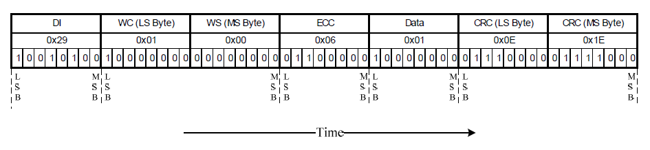
For the DI, highest 2 bits are virtual channel ID (VC), used when there are mutliple devices sharing the same DSI link, typically 0. The lower 6 bits are data type (DT), which could be one of the predefined values.
ECC is only for the 3 header bytes, which could be calculated as following:
P7 = 0
P6 = 0
P5 = D10^D11^D12^D13^D14^D15^D16^D17^D18^D19^D21^D22^D23
P4 = D4^D5^D6^D7^D8^D9^D16^D17^D18^D19^D20^D22^D23
P3 = D1^D2^D3^D7^D8^D9^D13^D14^D15^D19^D20^D21^D23
P2 = D0^D2^D3^D5^D6^D9^D11^D12^D15^D18^D20^D21^D22
P1 = D0^D1^D3^D4^D6^D8^D10^D12^D14^D17^D20^D21^D22^D23
P0 = D0^D1^D2^D4^D5^D7^D10^D11^D13^D16^D20^D21^D22^D23
Example implementation in Z80 assembly:
; name: dsi_ecc
; description:
;   calculate DSI packet header ECC checksum
; parameter:
;   B: first byte
;   C: second byte
;   D: third byte
; return:
;   A: forth byte (ECC byte)
; caller saved:
;   A, E, H, L
dsi_ecc__lut:
    ; ECC LUT
    db $ef, $fc, $00
    db $df, $03, $f0
    db $b8, $e3, $8e
    db $74, $9a, $6d
    db $f2, $55, $5b
    db $f1, $2c, $b7

dsi_ecc:
    ld hl, dsi_ecc__lut
    ld e, 6
    ld a, 0
    ccf
dsi_ecc__loop:
    ; save the iterator and arguments
    push bc
    push de
    ; save the result of last round
    push af
    ; load the lut and calculate this round
    ld a, [hl+]
    and a, b
    call byte_parity
    ld e, a
    ld a, [hl+]
    and a, c
    call byte_parity
    xor a, e
    ld e, a
    ld a, [hl+]
    and a, d
    call byte_parity
    xor a, e
    ; now a have the result of this round
    ld e, a
    ; fetch last round result and shift left
    pop af
    sla a
    ; combine the result from this round
    or a, e
    ; restor the iterator and arguments
    pop de
    pop bc
    dec e
    jr nz, dsi_ecc__loop
    ; finished
    ret
CRC for long packet is not discussed here. In practice it's generally fine to set them to 0.
Command mode and video mode
Conceptually, DSI transfer could be roughly divided into 2 modes, command mode and video mode. The command mode is similar to the DBI screen. Command or data could be sent to the screen, to writing controller registers like power or display mode, or writing pixels to the controller display RAM. These packets are not synchronized to the screen's scanning, so there is no limitation/ requirement on the data rate. Video mode is similar to DPI screen, the data is always continuous pixel data and HVsync. HVsync signals controls the screen scanning, so the date rate must match the pixel rate (at desired refresh rate, like 60Hz). DSI supports both, and typically screen needs both: command mode for configuring the power supply (and sometimes gamma), and video mode for transferring the image. The video mode is only valid in HS mode, however command mode is available in both LP and HS. Note that certain LCD controllers may not accept commands in HS mode, so it's recommended to send commands only in LP mode.
The real difference between these 2 modes are just the packets being sent, so there is "mode switching" like between the LP and HS mode.
There are 3 common data types in command mode:
- 0x05 DCS Short WRITE, no parameters.
- 0x15 DCS Short WRITE, 1 parameter.
- 0x39 DCS Long WRITE
The first two are short packets, and the last is a long packet. The use is based on the command length.
For example, typically 0x29 is the display ON command. It doesn't have any parameters, so 0x05 packet is used, with data bytes being 0x29 and 0x00. As another example, set display function command, 0xb6, with parameter 0x8a, 0x07, and 0x27. For this, 0x39 packet is used, with 2nd/3rd bytes set to 0x04, 0x00, meaning the payload is 4 bytes. 0xb6, 0x8a, 0x07, and 0x27 would be the payload.
There are 9 common data types in video modes. The following are for sending synchronization signals, all of them are short packets:
- 0x01 V Sync Start
- 0x11 V Sync End
- 0x21 H Sync Start
- 0x31 H Sync End
The following are for sending pixels, all of which are long packets:
- 0x19 Blanking Packet
- 0x0e Packed Pixel Stream, 16-bit RGB
- 0x1e Packed Pixel Stream, 18-bit RGB
- 0x2e Loosely Packed Pixel Stream, 18-bit RGB
- 0x3e Packed Pixel Stream, 24-bit RGB
These packets could be used to reconstruct the DPI signal. Start packets sets the signal to valid, and end packets sets it to be invalid. Blanking packet sends pixels with DE being invalid. Pixel stream sends pixels with DE valid. Notably, in DSI, Vsync start and vsync end would imply hsync start, so no hsync start is not sent during the first line. Start could also be treated as the valid edge of the sync signal, so end packets are optional.
Video timing
The video timing of DSI is similar to that of VGA and DPI:
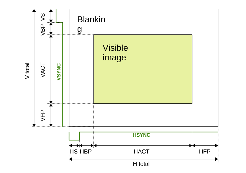
The sequence of a frame in pseudocode:
// DSI
#define V_SYNC_START         0x01
#define V_SYNC_END           0x11
#define H_SYNC_START         0x21
#define H_SYNC_END           0x31
#define BLANKING             0x19
#define PIXEL_STREAM_16BPP   0x0e
#define PIXEL_STREAM_24BPP   0x3e

// Standard VGA
#define V_TOTAL              525
#define VS                   2
#define VBP                  33
#define VACT                 480
#define VFP                  10
#define H_TOTAL              800
#define HS                   96
#define HBP                  48
#define HACT                 640
#define HFP                  16

// 16BPP
#define BPP                  2
#define PIXEL_STREAM         PIXEL_STREAM_16BPP
uint16_t pixel[VACT * HACT];

for (int y = 0; y < V_TOTAL; y++) {
    if (y == 0)
        dsi_short_packet(V_SYNC_START, 0x00, 0x00);
    else if (y == VS)
        dsi_short_packet(V_SYNC_END, 0x00, 0x00);
    else
        dsi_short_packet(H_SYNC_START, 0x00, 0x00);
    dsi_long_packet(BLANKING, HS * BPP, empty_buffer);
    dsi_short_packet(H_SYNC_END, 0x00, 0x00);
    dsi_long_packet(BLANKING, HBP * BPP, empty_buffer);
    if ((y >= (VS + VBP)) && (y < (VS + VBP + VACT)))
        dsi_long_packet(PIXEL_STREAM, HACT * BPP, &(pixel[(y - VBP - VS) * HACT * BPP]));
    else
        dsi_long_packet(BLANKING, HACT * BPP, empty_buffer);
    dsi_long_packet(BLANKING, HFP * BPP);
}
Initialization
Overall, the screen initialization sequence should be as the following:
- Reset the controller, either using RST or software reset using LPDT
- Initialize the screen controller using DCS/ generic data write
- Enable high speed clock on clock lines
- Start video timing, output video signal
Conclusion
None.