Note: this post is also available in video format on YouTube. Some demo/ difference would be more obvious in video.
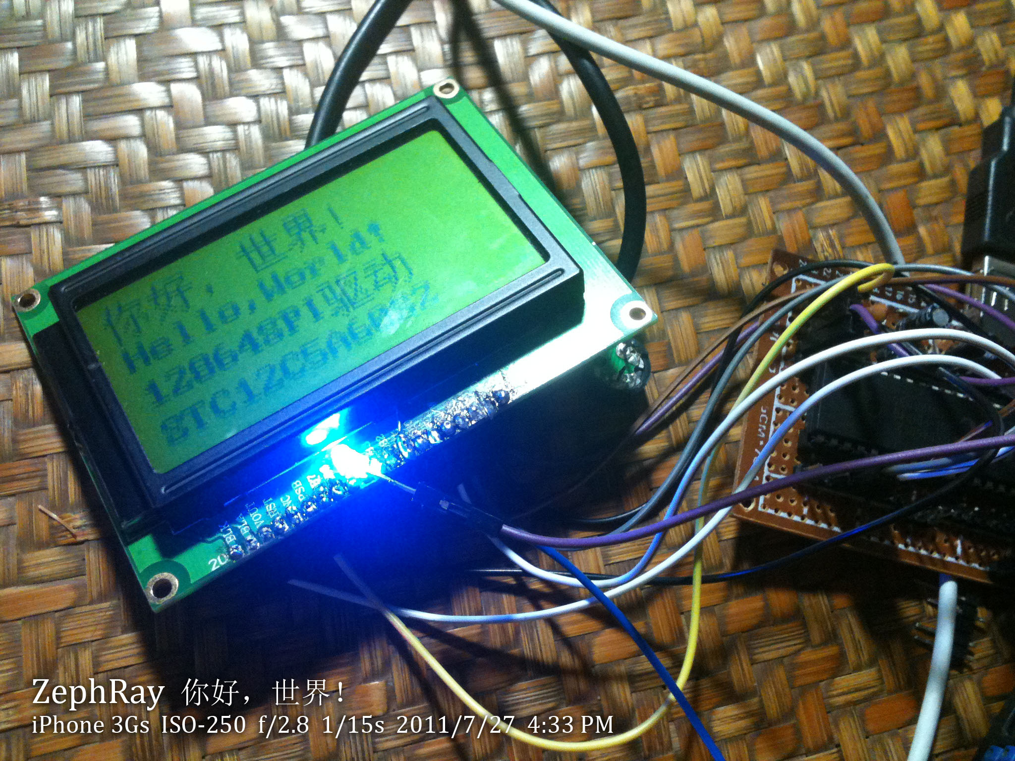
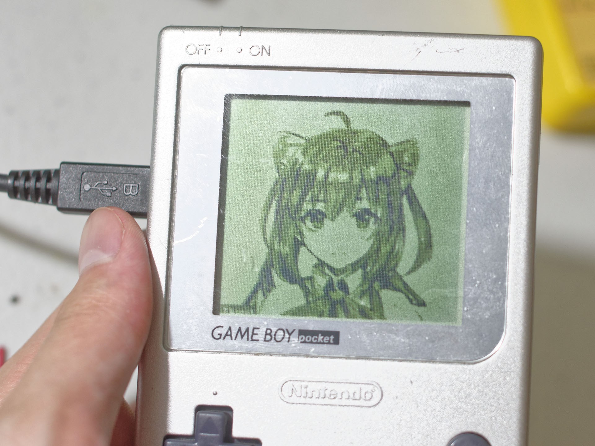
If you've been following this blog lately, you've probably noticed there is a series of blog posts called LetsDriveLCD where I buy random LCDs and drive them to display something. Most of them are passive dot-matrix LCDs: the reflective monochrome screens with a green-ish tint. Many portable devices made late last century and early 2000s featured this type of display. While they are almost extinct on modern consumer electronic devices, they could still be easily found on various embedded devices.
I am always fascinated by the distinct look of these screens. So I picked up a few of these screens online, and started learning microcontrollers to drive them. That was more than 10 years ago.
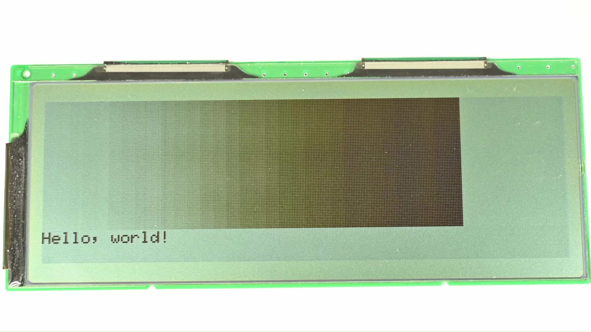
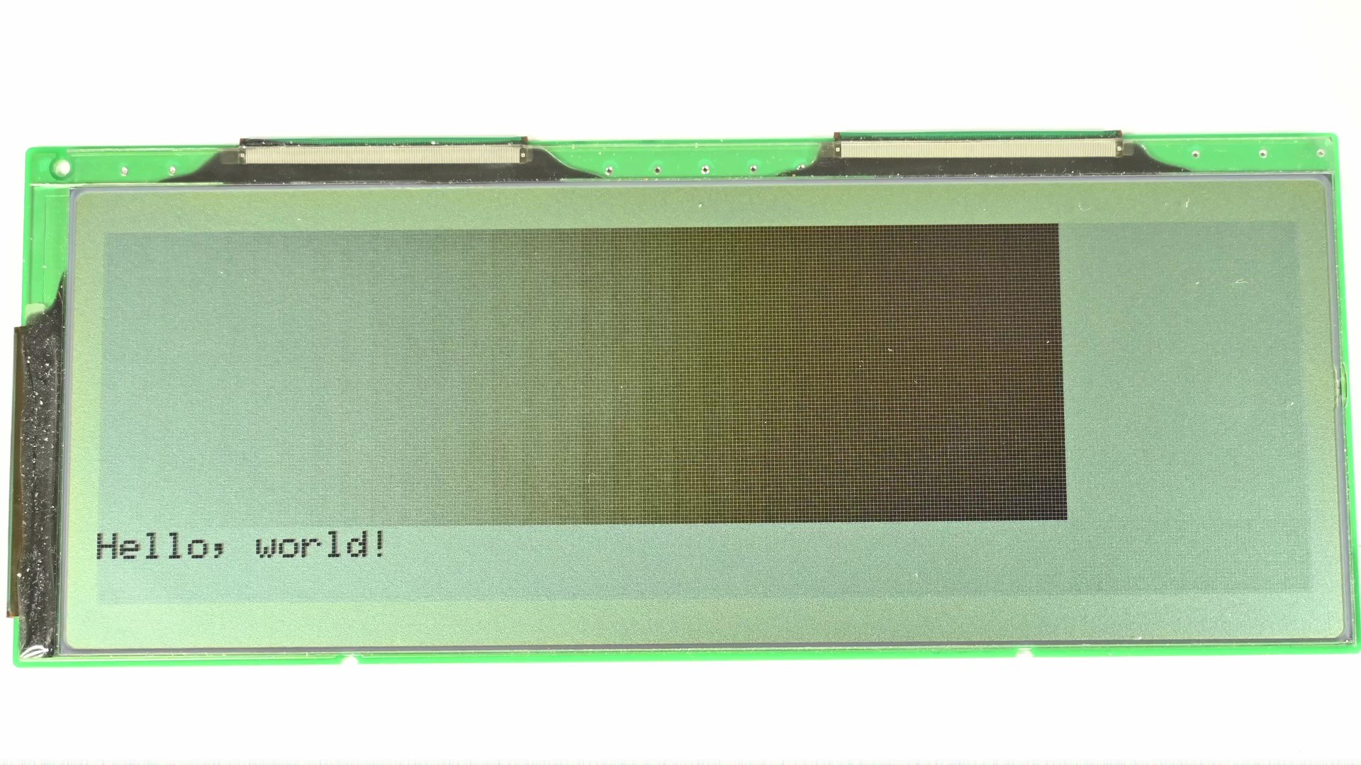
Today I am going to do something similar, driving a 320 by 100 pixel reflective FSTN LCD screen, with de-facto industrial standard STN LCD pixel interface. First try display the following image:

And this is the… result.
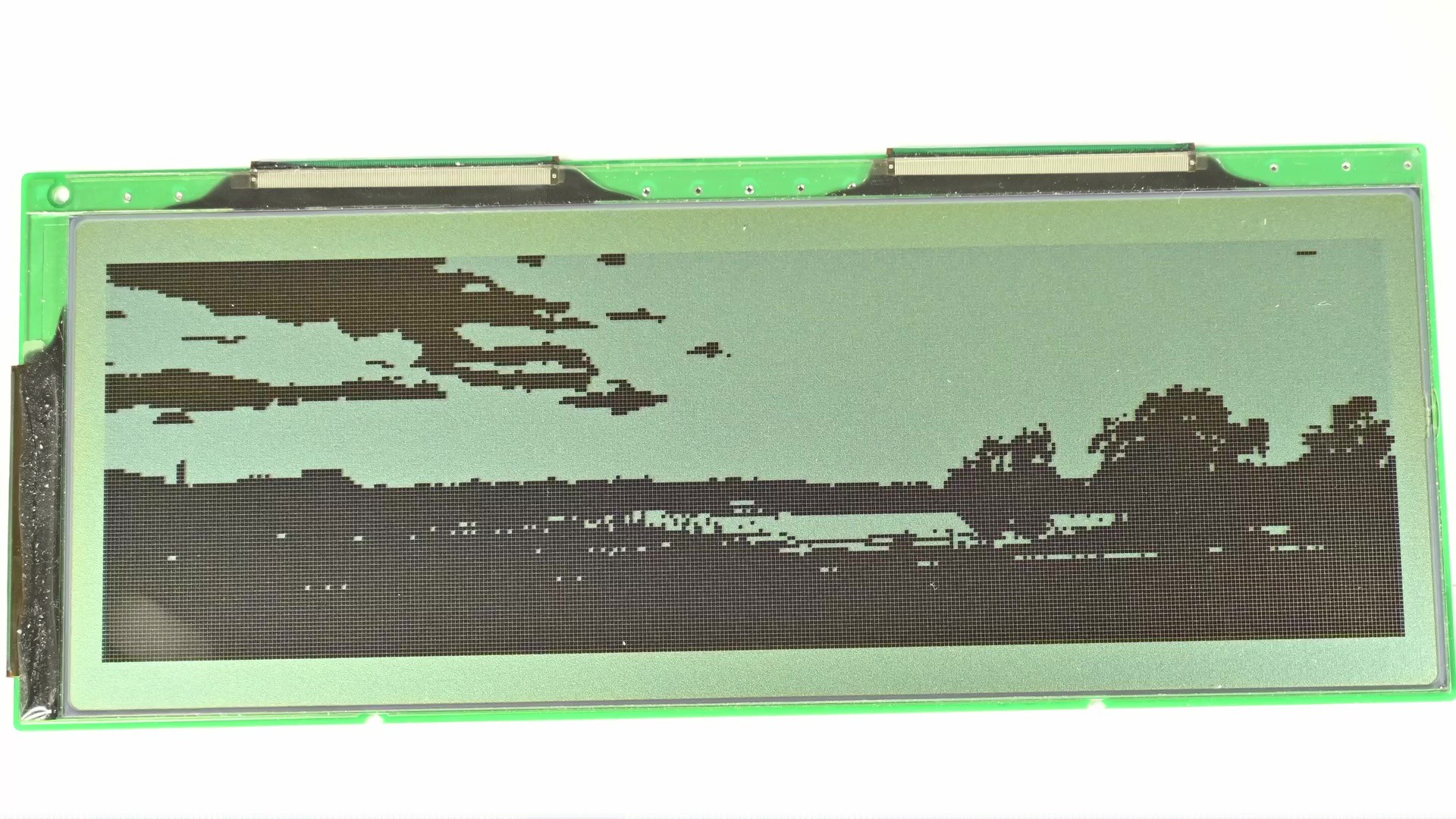
The issue is obvious, the screen is 1-bit monochrome, so for each pixel it could only be either on or off, without any gray shades in between. If I just directly display the image by clamping the pixel value to 0 or 1, it would look like this.
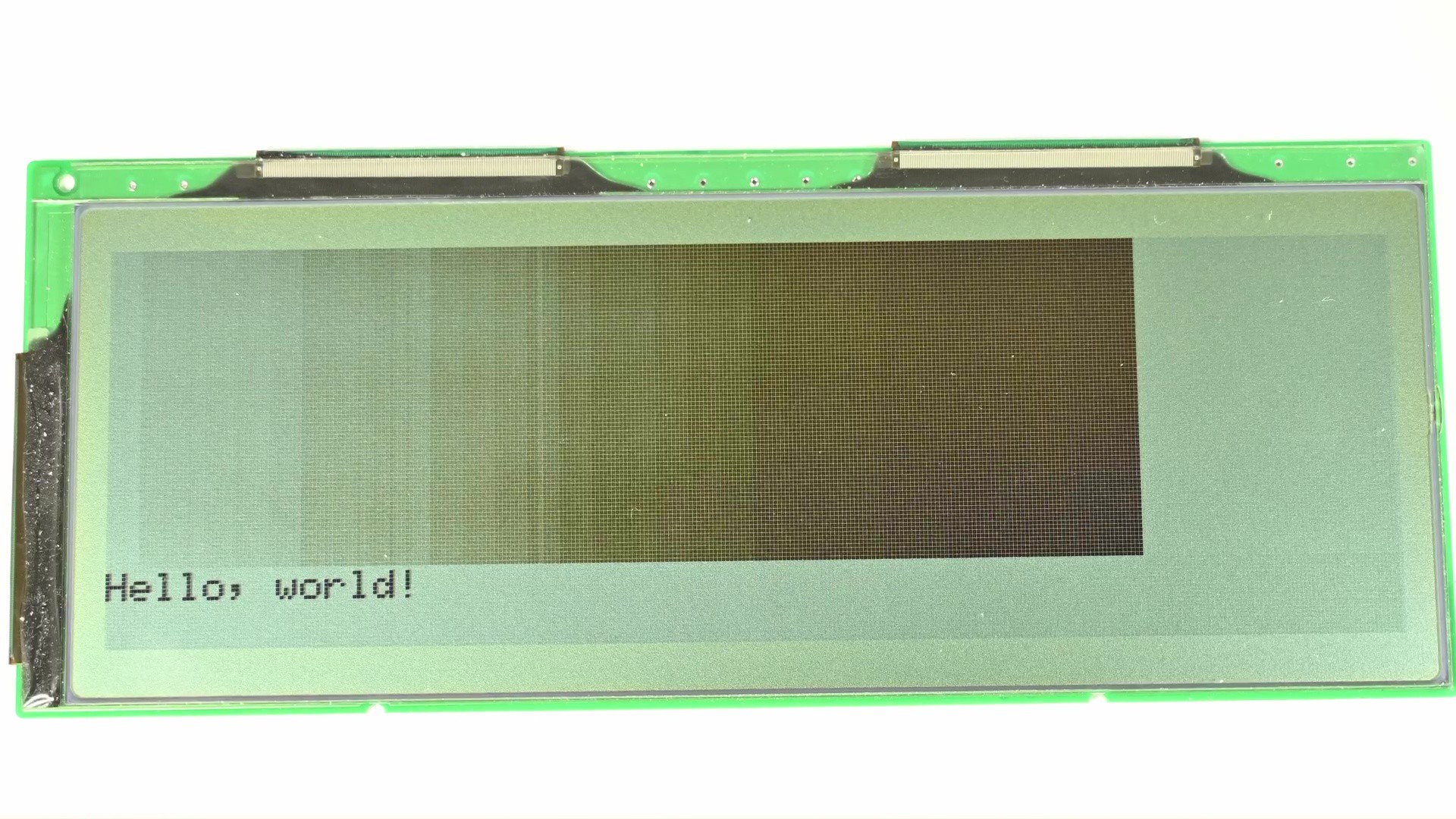
The good news is I could do better. Displaying images with a limited color palette is a well researched and understood topic, and one of the answers is to do dithering. The main idea is to use diffusion of available colors to create approximation of colors not available from the color palette. For example if I were to apply dithering to the image, it would look like this.
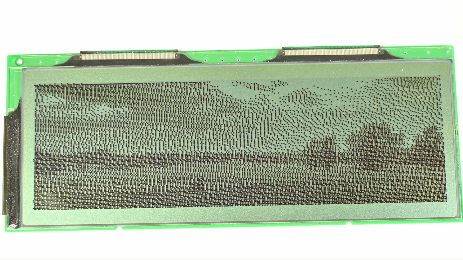
It’s still outputting to a 1-bit screen, but now I could see more details from the image compared to the direct clamping. There are many ways of doing the dithering, the one used here specifically is based on error diffusion. Let’s take a closer look.
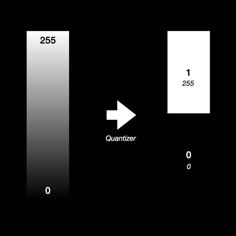
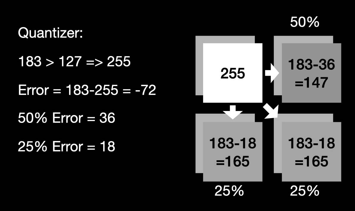
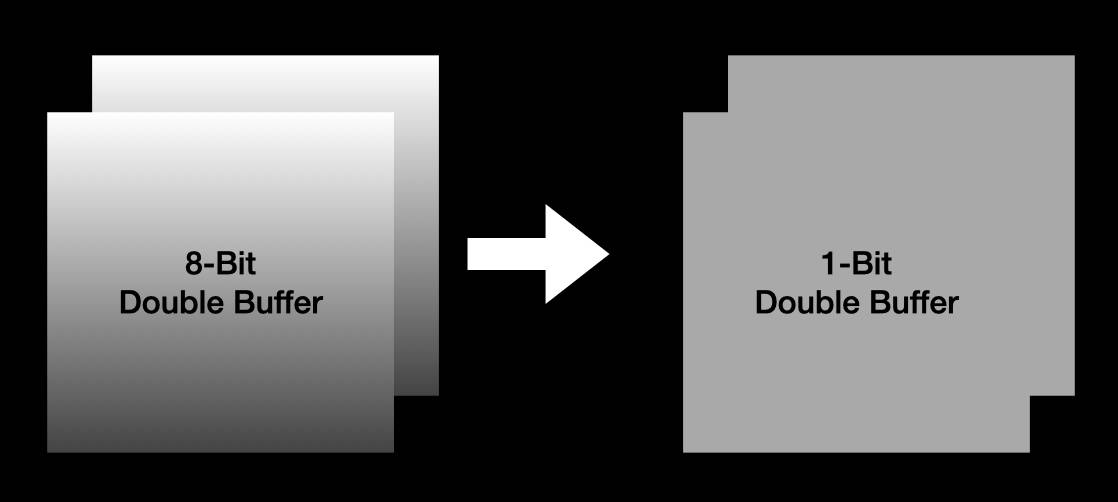
Say I have an input image, that’s 8-bit grayscale, and output is 1-bit. Or in otherways, if to represent the output in the input range, the output could be either 0 or 255. Anything in the middle is unavailable. To choose the output value based on input, a quantizer is introduced here: if the input is larger than a half, or 127, then it outputs 255, otherwise 0. This is what I have been doing before, clamping the image to black or white directly.
Now bringin the error diffusion on to the table. Each time the quantizer chooses an output value that’s different from the input, an error is introduced. The error is simply the difference between input and output. In the previous case, the error is simply dropped. However, if the goal is to minimize the error, then I should do something to compensate for the error. Error-diffusion means to diffuse the error to neighboring pixels. As a result, when the quantizer quantized these pixels, the error would have a chance to be compensated. This is what I’ve shown you before.
But something is off, I remember these screens could do many levels of grayscale, like on these devices they could all display different shades of gray or green. However, almost all of the screens I got were 1-bit mono. Initially I thought this is probably because the screen I got was for industry control or similar stuff so they don’t need that. Only the screen for consumer electronics would have greyscale support. Which turned out to be false. I took apart some devices that have 16 levels of grayscale and found out that the screens themselves are 1-bit screens. What’s the trick there? Let’s take a deep dive into this.
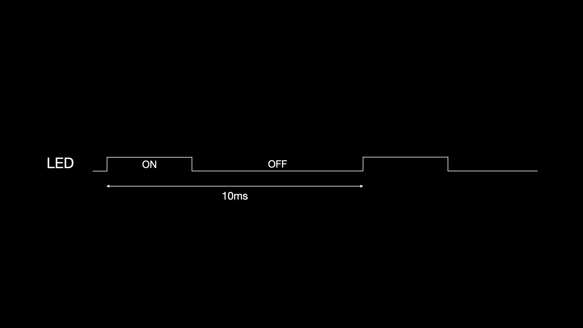
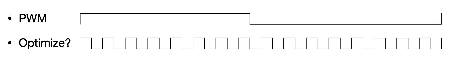
So now I am now given a screen that could either display black and white, and I would like to display different shades of gray on the screen. How to do that? Well if I use another analogy to that: I have a digital output pin which could be either high or low, and there is an LED connected to it. And instead of just lighting up or shutting off, I want to have a different brightness. Does this sound familiar? There is a commonly used technique called PWM for doing this. Basically define a period, and for some time in this period the output is high, and the rest is low. Then the whole period gets repeated over and over. If this is fast enough that eyes couldn’t detect, one would think it’s some brightness in the middle, instead of it being switched on and off rapidly.
Can I do the same on these monochrome LCDs? Yes and no. There are some LCDs that have PWM built into the driver chip, so they natively take multiple bits per pixel as input, and would modulate the greyscale during the screen refreshing process. One example is that GameBoy’s screen takes 2 bit per pixel input natively and produces 4 level grayscale.
However based on my observation this is not that common, most other screens like the one on PDAs or old laptops typically only take 1-bit per pixel input and only do black and white natively.
Well then if the screen driver chip doesn’t have PWM built-in, can I still use PWM on a maybe higher level? You see, LCD, to keep display, needs to be constantly refreshed. So if I look at a single pixel, it’s being driven at a constant interval, and I have control over the level, being either high or low. In this sense, I could simply put a PWM waveform there.
For example, if I want 16 level grayscale, then I can have a PWM period of 15, then based on the output level, the duty cycle would be 0 to 15 cycles. Sounds great. Does it work? Let’s see.
To code it, there are 1 bit-per-pixel frame buffers that would be sent to the screen. And there are 8 bit-per-pixel frame buffers that would hold the grayscale image to be displayed. Now I just need to write a function that does the software PWM on these buffers.
So I set up a PWM period counter, which goes from 0 to 14, incrementing on each frame. Then in a loop, for each pixel, it compares the incoming pixel value with the counter value, if larger it outputs 1, otherwise 0. So with different pixel values it would output a different duty cycle on each pixel.
uint32_t framecnt = 0;

static inline uint8_t handle_pixel(uint8_t color) {
    return ((color / 16) > framecnt);
}

static void process_frame() {
    for (int i = 0; i < X * Y; i++) {
        outp[i] = handle_pixel(inp[i]);
    }
    framecnt++;
    if (framecnt == 15)
        framecnt = 0;
}
Now let’s run it and see how it looks.
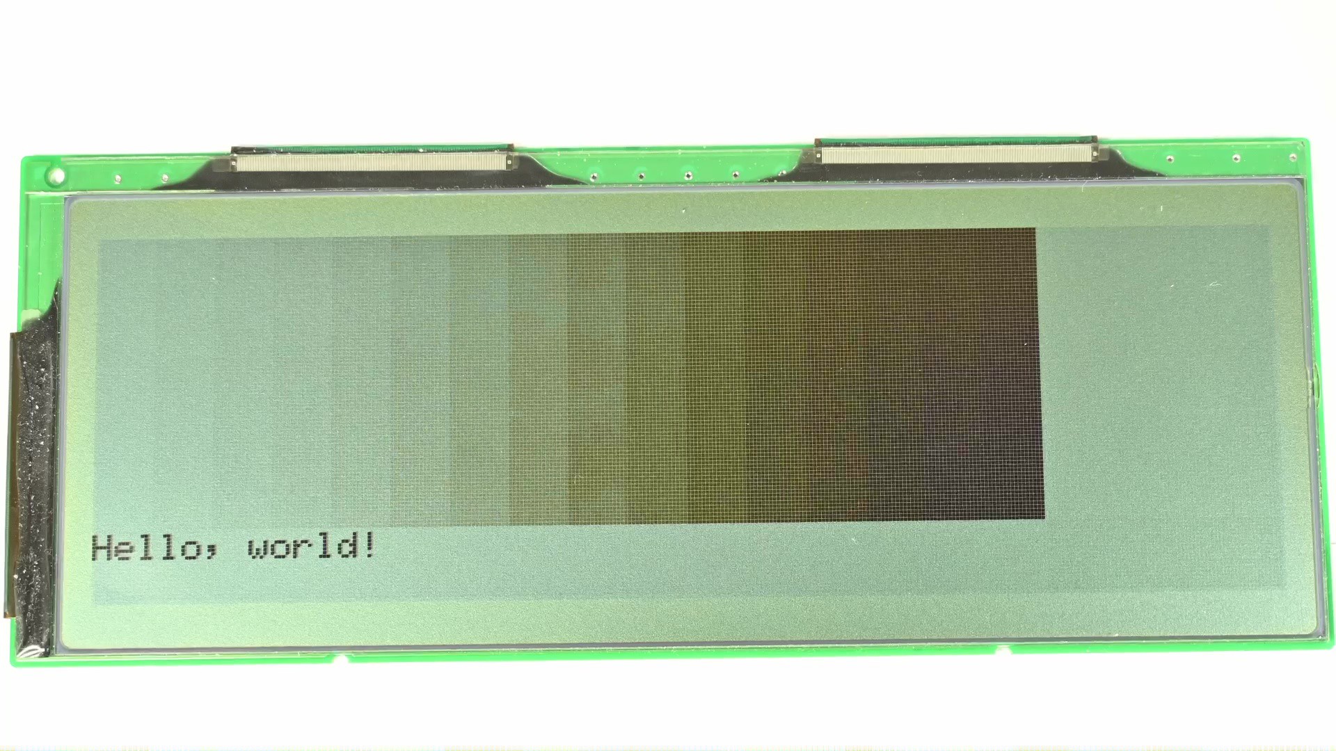
While it probably looks decent in the picture, actually the image is quite flickery and the reason should be obvious. The minimum unit of output is a frame, or at 120Hz refresh rate, about 8.3ms. If the PWM period is 15 cycles, that’s 15 frames, or 124.5 ms total. This translates to a PWM frequency of only 8 Hz, surely it would flicker pretty bad. I could reduce the PWM period down to say 3, so the PWM frequency is up to 40Hz for a sort of steady image. But obviously the grayscale level is then reduced to 4 levels.
I get grayscale and it’s all good now right? Something is still off. I know these devices could get 16 level or even high levels of grayscale out of these 1-bit screens. So there must be a better way to do that. After reading some papers, I found out typically this is done by using optimized sequences. For example when outputting the 50% gray, if the PWM period is set to like 16, it would be 8 cycles high and 8 cycles low, then repeat. But to reduce flicker, it could be just 1 cycle high and 1 cycle low, then repeat, still maintaining the same 50% duty cycle.
Sounds great so let’s implement that. I designed some naive sequences for 32 level grayscale. The duty cycle linearly corresponds to the pixel value.
const static unsigned char gldp[] = {
        0, 0, 0, 0, 0, 0, 0, 0, 0, 0, 0, 0, 0, 0, 0, 0, 0, 0, 0, 0, 0, 0, 0, 0, 0, 0, 0, 0, 0, 0, 0,
        1, 0, 0, 0, 0, 0, 0, 0, 0, 0, 0, 0, 0, 0, 0, 0, 0, 0, 0, 0, 0, 0, 0, 0, 0, 0, 0, 0, 0, 0, 0,
        1, 0, 0, 0, 0, 0, 0, 0, 0, 0, 0, 0, 0, 0, 0, 1, 0, 0, 0, 0, 0, 0, 0, 0, 0, 0, 0, 0, 0, 0, 0,
        1, 0, 0, 0, 0, 0, 0, 0, 0, 0, 1, 0, 0, 0, 0, 0, 0, 0, 0, 0, 0, 1, 0, 0, 0, 0, 0, 0, 0, 0, 0,
        1, 0, 0, 0, 0, 0, 0, 0, 1, 0, 0, 0, 0, 0, 0, 0, 1, 0, 0, 0, 0, 0, 0, 0, 1, 0, 0, 0, 0, 0, 0,
        1, 0, 0, 0, 0, 0, 1, 0, 0, 0, 0, 0, 1, 0, 0, 0, 0, 0, 1, 0, 0, 0, 0, 0, 1, 0, 0, 0, 0, 0, 0,
        1, 0, 0, 0, 0, 1, 0, 0, 0, 0, 1, 0, 0, 0, 0, 1, 0, 0, 0, 0, 1, 0, 0, 0, 0, 1, 0, 0, 0, 0, 0,
        1, 0, 0, 0, 1, 0, 0, 0, 0, 1, 0, 0, 0, 1, 0, 0, 0, 0, 1, 0, 0, 0, 1, 0, 0, 0, 0, 1, 0, 0, 0,
        1, 0, 0, 0, 1, 0, 0, 0, 1, 0, 0, 0, 1, 0, 0, 0, 1, 0, 0, 0, 1, 0, 0, 0, 1, 0, 0, 0, 1, 0, 0,
        1, 0, 0, 1, 0, 0, 0, 1, 0, 0, 1, 0, 0, 0, 1, 0, 0, 1, 0, 0, 0, 1, 0, 0, 1, 0, 0, 0, 1, 0, 0,
        1, 0, 0, 1, 0, 0, 1, 0, 0, 1, 0, 0, 1, 0, 0, 1, 0, 0, 1, 0, 0, 1, 0, 0, 1, 0, 0, 1, 0, 0, 0,
        1, 0, 0, 1, 0, 0, 1, 0, 0, 1, 0, 0, 1, 0, 0, 1, 0, 0, 1, 0, 0, 1, 0, 0, 1, 0, 0, 1, 0, 0, 1,
        1, 0, 1, 0, 0, 1, 0, 1, 0, 0, 1, 0, 1, 0, 0, 1, 0, 0, 1, 0, 0, 1, 0, 1, 0, 0, 1, 0, 1, 0, 0,
        1, 0, 1, 0, 1, 0, 0, 1, 0, 1, 0, 1, 0, 0, 1, 0, 1, 0, 1, 0, 0, 1, 0, 1, 0, 1, 0, 0, 1, 0, 0,
        1, 0, 1, 0, 1, 0, 1, 0, 1, 0, 0, 1, 0, 1, 0, 1, 0, 1, 0, 0, 1, 0, 1, 0, 1, 0, 1, 0, 1, 0, 0,
        1, 0, 1, 0, 1, 0, 1, 0, 1, 0, 1, 0, 1, 0, 1, 0, 1, 0, 1, 0, 1, 0, 1, 0, 1, 0, 1, 0, 1, 0, 0,
        0, 1, 0, 1, 0, 1, 0, 1, 0, 1, 0, 1, 0, 1, 0, 1, 0, 1, 0, 1, 0, 1, 0, 1, 0, 1, 0, 1, 0, 1, 1,
        0, 1, 0, 1, 0, 1, 0, 1, 0, 1, 1, 0, 1, 0, 1, 0, 1, 0, 1, 1, 0, 1, 0, 1, 0, 1, 0, 1, 0, 1, 1,
        0, 1, 0, 1, 0, 1, 1, 0, 1, 0, 1, 0, 1, 1, 0, 1, 0, 1, 0, 1, 1, 0, 1, 0, 1, 0, 1, 1, 0, 1, 1,
        0, 1, 0, 1, 1, 0, 1, 0, 1, 1, 0, 1, 0, 1, 1, 0, 1, 1, 0, 1, 1, 0, 1, 0, 1, 1, 0, 1, 0, 1, 1,
        0, 1, 1, 0, 1, 1, 0, 1, 1, 0, 1, 1, 0, 1, 1, 0, 1, 1, 0, 1, 1, 0, 1, 1, 0, 1, 1, 0, 1, 1, 0,
        0, 1, 1, 0, 1, 1, 0, 1, 1, 0, 1, 1, 0, 1, 1, 0, 1, 1, 0, 1, 1, 0, 1, 1, 0, 1, 1, 0, 1, 1, 1,
        0, 1, 1, 0, 1, 1, 1, 0, 1, 1, 0, 1, 1, 1, 0, 1, 1, 0, 1, 1, 1, 0, 1, 1, 0, 1, 1, 1, 0, 1, 1,
        0, 1, 1, 1, 0, 1, 1, 1, 0, 1, 1, 1, 0, 1, 1, 1, 0, 1, 1, 1, 0, 1, 1, 1, 0, 1, 1, 1, 0, 1, 1,
        0, 1, 1, 1, 0, 1, 1, 1, 1, 0, 1, 1, 1, 0, 1, 1, 1, 1, 0, 1, 1, 1, 0, 1, 1, 1, 1, 0, 1, 1, 1,
        0, 1, 1, 1, 1, 0, 1, 1, 1, 1, 0, 1, 1, 1, 1, 0, 1, 1, 1, 1, 0, 1, 1, 1, 1, 0, 1, 1, 1, 1, 1,
        0, 1, 1, 1, 1, 1, 0, 1, 1, 1, 1, 1, 0, 1, 1, 1, 1, 1, 0, 1, 1, 1, 1, 1, 0, 1, 1, 1, 1, 1, 1,
        0, 1, 1, 1, 1, 1, 1, 1, 0, 1, 1, 1, 1, 1, 1, 1, 0, 1, 1, 1, 1, 1, 1, 1, 0, 1, 1, 1, 1, 1, 1,
        0, 1, 1, 1, 1, 1, 1, 1, 1, 1, 0, 1, 1, 1, 1, 1, 1, 1, 1, 1, 1, 0, 1, 1, 1, 1, 1, 1, 1, 1, 1,
        0, 1, 1, 1, 1, 1, 1, 1, 1, 1, 1, 1, 1, 1, 1, 0, 1, 1, 1, 1, 1, 1, 1, 1, 1, 1, 1, 1, 1, 1, 1,
        0, 1, 1, 1, 1, 1, 1, 1, 1, 1, 1, 1, 1, 1, 1, 1, 1, 1, 1, 1, 1, 1, 1, 1, 1, 1, 1, 1, 1, 1, 1,
        1, 1, 1, 1, 1, 1, 1, 1, 1, 1, 1, 1, 1, 1, 1, 1, 1, 1, 1, 1, 1, 1, 1, 1, 1, 1, 1, 1, 1, 1, 1,
};
Some may recognize this and say, isn’t this just mimicking PDM? Yes it is but hold on to it for now. The code for using such sequences is also straightforward. Again I keep a period counter, from 0 to 30. Instead of directly comparing the pixel value with counter value to produce a PWM waveform, both are used as index into the sequence look up table to derive the value to use.
#define GLDP_LENGTH 31
uint32_t framecnt = 0;

static inline uint8_t handle_pixel(uint8_t color) {
    return gldp[color * GLDP_LENGTH + framecnt];
}

static void process_frame() {
    for (int i = 0; i < X * Y; i++) {
        outp[i] = handle_pixel(inp[i]);
    }
    framecnt++;
    if (framecnt == GLDP_LENGTH)
        framecnt = 0;
}
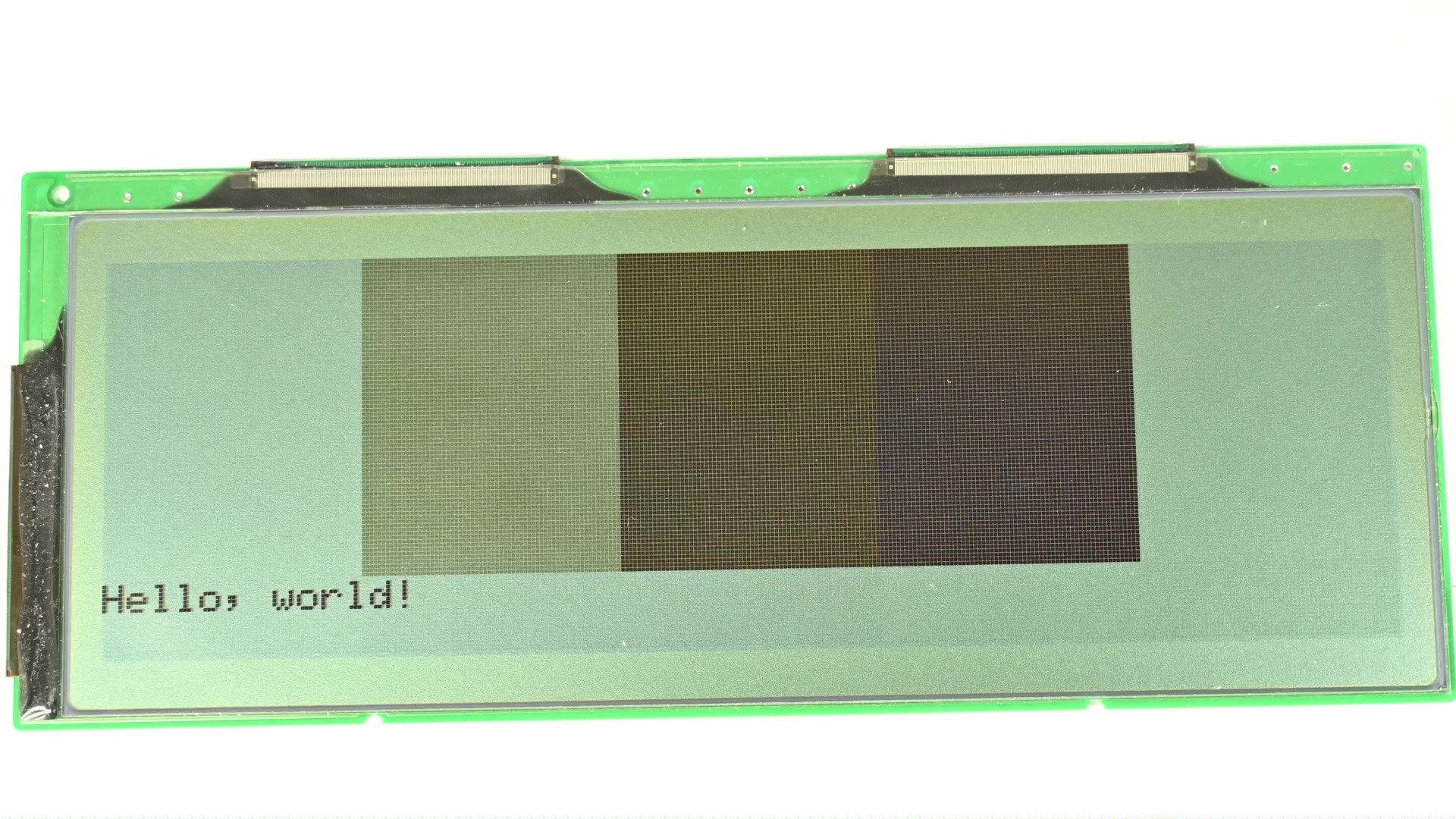
Now running the code, I am almost getting 32 grayscale levels. Except some levels are still flicky. This is totally understandable, for these levels, the optimization doesn’t improve much. For example in the extreme case of the lightest level that’s not pure white, that just 1 pulse in 31 cycles. It doesn’t matter where you put that pulse.
Then what’s next? What to do with these flickery levels? Well there are 2 possible ways to fix that. One is to simply not use these duty cycles. In the sequences I crafted, the duty cycle linearly corresponds to the input gray level. This is not really required and this is also not what’s typically done. There are many duty cycles that have a shorter period but are not used in this 31 frame sequence. For example, like 5/9, 3/5, 3/4, 7/8, etc. I could use these sequences to replace ones that’s too flickery. I also don’t have to start with 1 pulse, I could start with a, say 1/8 duty cycle at the lightest gray level.
const uint8_t gldp_g0[]  = {1, 0}; // 0, 0
const uint8_t gldp_g1[]  = {9, 0, 0, 0, 0, 0, 0, 0, 0, 1}; // 1, 1/9
const uint8_t gldp_g2[]  = {8, 0, 0, 0, 0, 0, 0, 0, 1}; // 2, 1/8
const uint8_t gldp_g3[]  = {7, 0, 0, 0, 0, 0, 0, 1}; // 3, 1/7
const uint8_t gldp_g4[]  = {6, 0, 0, 0, 0, 0, 1}; // 4, 1/6
const uint8_t gldp_g5[]  = {5, 0, 0, 0, 0, 1}; // 5, 1/5
const uint8_t gldp_g6[]  = {4, 0, 0, 0, 1}; // 6, 1/4
const uint8_t gldp_g7[]  = {7, 0, 0, 0, 1, 0, 0, 1}; // 7, 2/7
const uint8_t gldp_g8[]  = {10, 0, 0, 0, 1, 0, 0, 1, 0, 0, 1}; // 8, 3/10
const uint8_t gldp_g9[]  = {3, 0, 0, 1}; // 9, 1/3
const uint8_t gldp_g10[] = {8, 0, 1, 0, 0, 1, 0, 0, 1}; // 3/8
const uint8_t gldp_g11[] = {5, 0, 0, 1, 0, 1}; // 2/5
const uint8_t gldp_g12[] = {9, 0, 0, 1, 0, 1, 0, 1, 0, 1}; // 4/9
const uint8_t gldp_g13[] = {13, 0, 0, 1, 0, 1, 0, 1, 0, 1, 0, 1}; // 6/13
const uint8_t gldp_g14[] = {2, 0, 1}; // 1/2
const uint8_t gldp_g15[] = {13, 0, 1, 0, 1, 0, 1, 1, 0, 0, 1, 0, 1, 1}; // 7/13
const uint8_t gldp_g16[] = {9, 1, 0, 1, 0, 1, 0, 1, 0, 1}; // 5/9
const uint8_t gldp_g17[] = {5, 1, 0, 1, 0, 1}; // 3/5
const uint8_t gldp_g18[] = {11, 0, 1, 1, 0, 1, 1, 0, 1, 1, 0, 1}; // 7/11
const uint8_t gldp_g19[] = {3, 0, 1, 1}; // 2/3
const uint8_t gldp_g20[] = {13, 1, 1, 0, 1, 1, 0, 1, 1, 0, 1, 1, 0, 1}; // 9/13
const uint8_t gldp_g21[] = {8, 1, 1, 1, 0, 1, 1, 1, 0, 1, 1, 0}; // 8/11
const uint8_t gldp_g22[] = {4, 1, 1, 1, 0}; // 3/4
const uint8_t gldp_g23[] = {9, 1, 1, 1, 0, 1, 1, 1, 0, 1}; // 7/9
const uint8_t gldp_g24[] = {5, 1, 1, 0, 1, 1}; // 4/5
const uint8_t gldp_g25[] = {6, 1, 1, 1, 0, 1, 1}; // 5/6
const uint8_t gldp_g26[] = {7, 0, 1, 1, 1, 1, 1, 1}; // 6/7
const uint8_t gldp_g27[] = {9, 0, 1, 1, 1, 1, 1, 1, 1, 1}; // 8/9
const uint8_t gldp_g28[] = {11, 0, 1, 1, 1, 1, 1, 1, 1, 1, 1, 1}; // 10/11
const uint8_t gldp_g29[] = {15, 0, 1, 1, 1, 1, 1, 1, 1, 1, 1, 1, 1, 1, 1, 1}; // 14/15
const uint8_t gldp_g30[] = {31, 0, 1, 1, 1, 1, 1, 1, 1, 1, 1, 1, 1, 1, 1, 1, 1, 1, 1, 1, 1, 1, 1, 1, 1, 1, 1, 1, 1, 1, 1, 1}; // 30/31
const uint8_t gldp_g31[] = {1, 1};
This would obviously screw up the linearity, but the screen response is not linear to begin with anyway. Now with a, probably better sequence table, run it again and see.
Yeah, maybe a bit better, but still far from good.
I said there are 2 ways to fix that, and now it’s time for method 2. Looking at the flickery shades, imagine if it’s just one pixel there, then it won’t be very obvious that it’s flicking. A block of pixels flick in the same way makes it especially easy to catch with eyes. In other words, if pixels are not being flipped at the same frame, then it won’t be that obvious. There are multiple ways to achieve that, like reversing or rotating the sequence table based on the pixel location, like if it’s even or odd, etc. Or, simply use some random function. I am going to just use an LFSR to add an offset to the sequence for each pixel. Remember to reset the LFSR each frame so each pixel always gets the same offset.
#define GLDP_LENGTH 31
uint32_t framecnt = 0;
static int random_select = 1;

static inline uint8_t handle_pixel(uint8_t color) {
    random_select = random_select / 2 ^ -(random_select % 2) & 0x428e;
    int sel = (framecnt + random_select) % GLDP_LENGTH;
    return gldp[color * GLDP_LENGTH + sel];
}

static void process_frame() {
    random_select = 1;
    for (int i = 0; i < X * Y; i++) {
        outp[i] = handle_pixel(inp[i]);
    }
    framecnt++;
    if (framecnt == GLDP_LENGTH)
        framecnt = 0;
}
Run it again, much better right?
This method of using a sequence table along with other optimizations to generate grayscale is typically called frame rate control, or FRC for short, while it doesn’t really control the frame rate at all. As a result, I have implemented what’s typically done on a grayscale LCD controller from last century. I have also got 32 levels of grayscale out of this 1-bit LCD. The difference is that typically these are implemented on hardware, but I am here emulating these with software. But as you could see from the video progress bar, I am not finished yet.
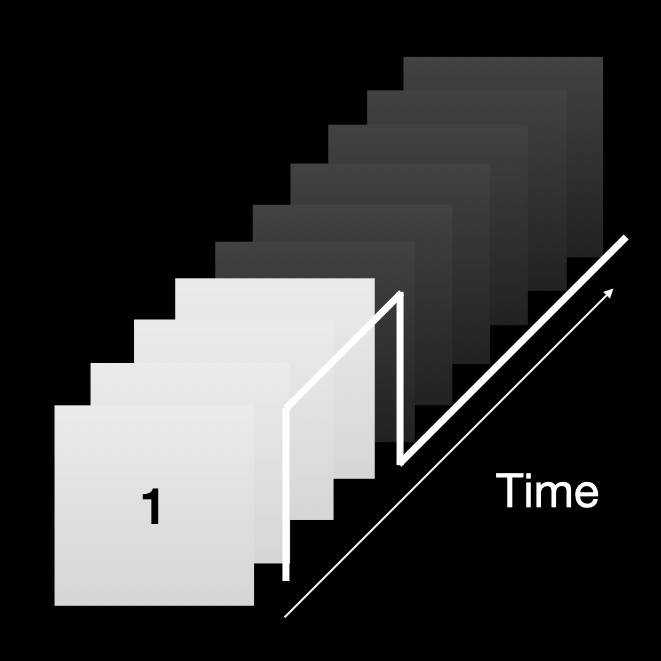
In the early part of the video, I introduced the concept of dithering. In fact all the stuff I have been talking about is dithering. The initial error-diffusion dithering I showed is spatial dithering, or, dither over an area, then later the PWM and greyscale sequence are temporal dithering, or dither over a period of time. Now thinking about the error diffusion, if it’s possible to diffuse error over an area, would it be possible to also diffuse the error over a period of time? Like a temporal error diffuser? Let’s try that as well!
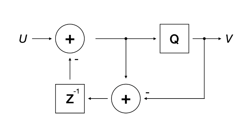
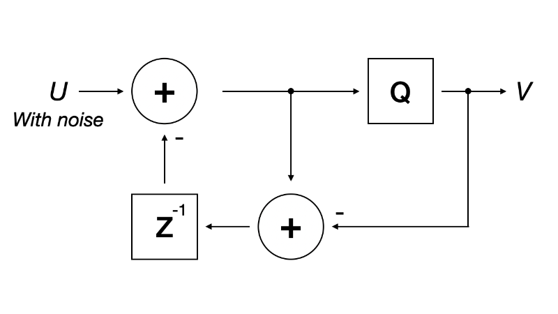
Back to this function, where it picks a value from the sequence table. Modify the code to quantize the pixel, then calculate the error value. But instead of diffusing the error to neighboring pixels, the error is accumulated in a per pixel error buffer. When the next frame comes, the quantizing error is added back to the quantizer input so that’s taken care of. Did I just re-invented a first-order delta-sigma modulator?
static inline uint8_t handle_pixel(uint8_t color, int8_t *perr) {
    int err = *perr;
    int c = (int)color + err;
    int output = (c > 15) ? 31 : 0;
    err = c - output;
    *perr = err;

    return !!output;
}

static void process_frame() {
    for (int i = 0; i < X * Y; i++) {
        outp[i] = handle_pixel(inp[i], &err[i]);
    }
}
I said before that the whole optimized sequence thing is just mimicking PDM or pulse density modulation, and now with a delta-sigma modulator I am getting a real PDM signal. Run it, does the result look familiar? Yes it’s very similar to the previous case with optimized sequence but without any randomness. If I were to add some randomness to it, by adding a +1 or -1 random number into the pixel each time, then we get some randomness. Looks pretty good.
Thinking about that again, adding a small random number is basically injecting a small noise. Hmmm, injecting noise to delta-sigma modulator, ah I just re-invented a 1st-order noise-shaper.
static inline uint8_t handle_pixel(uint8_t color, int8_t *perr) {
    static int noise = 1;
    noise = noise / 2 ^ -(noise % 2) & 0x428e;
    int err = *perr;
    int c = (int)color + err + (((noise & 0x1) << 1) - 1);
    int output = (c > 15) ? 31 : 0;
    err = c - output;
    *perr = err;

    return !!output;
}

static void process_frame() {
    for (int i = 0; i < X * Y; i++) {
        outp[i] = handle_pixel(inp[i], &err[i]);
    }
}
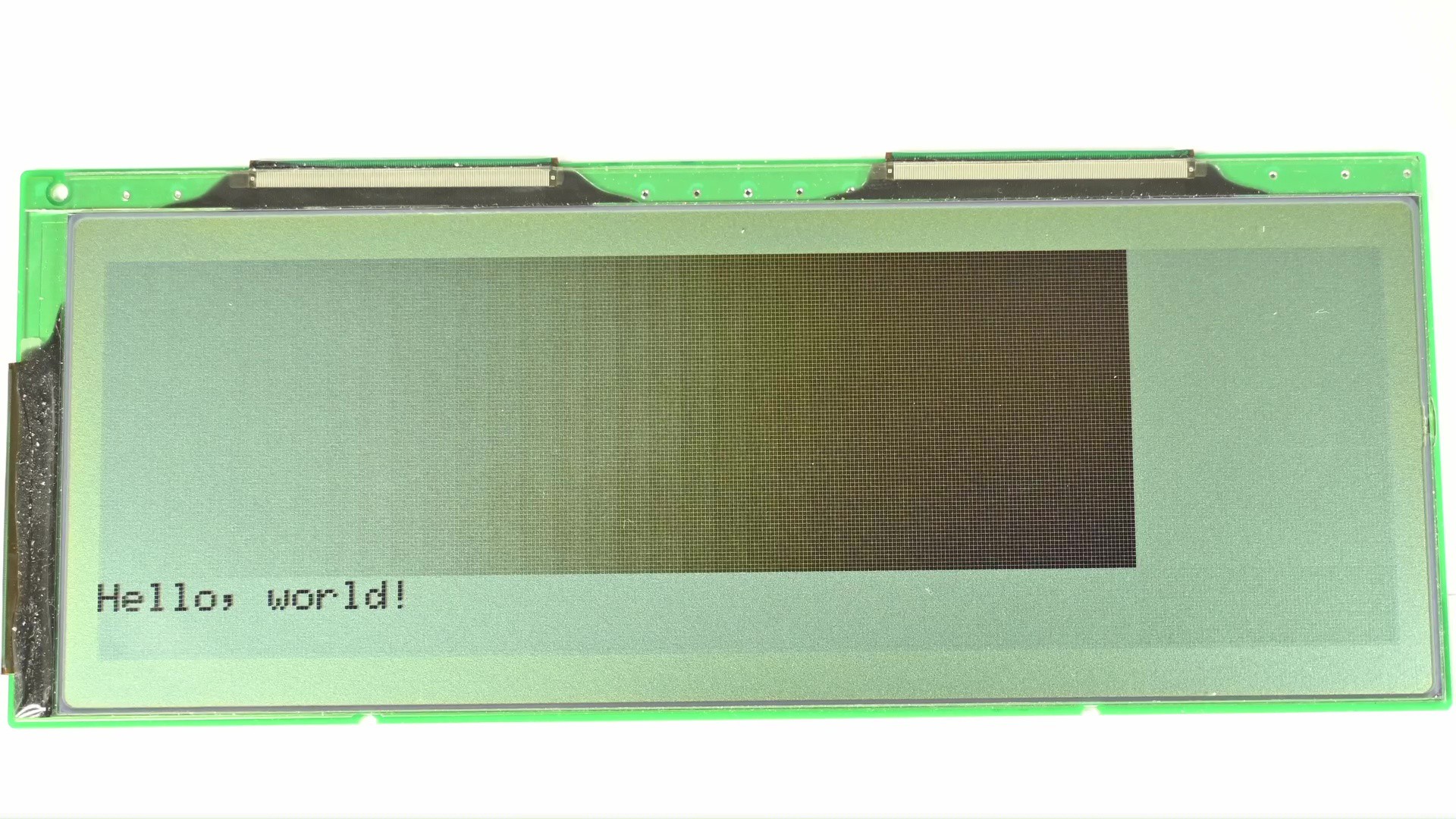
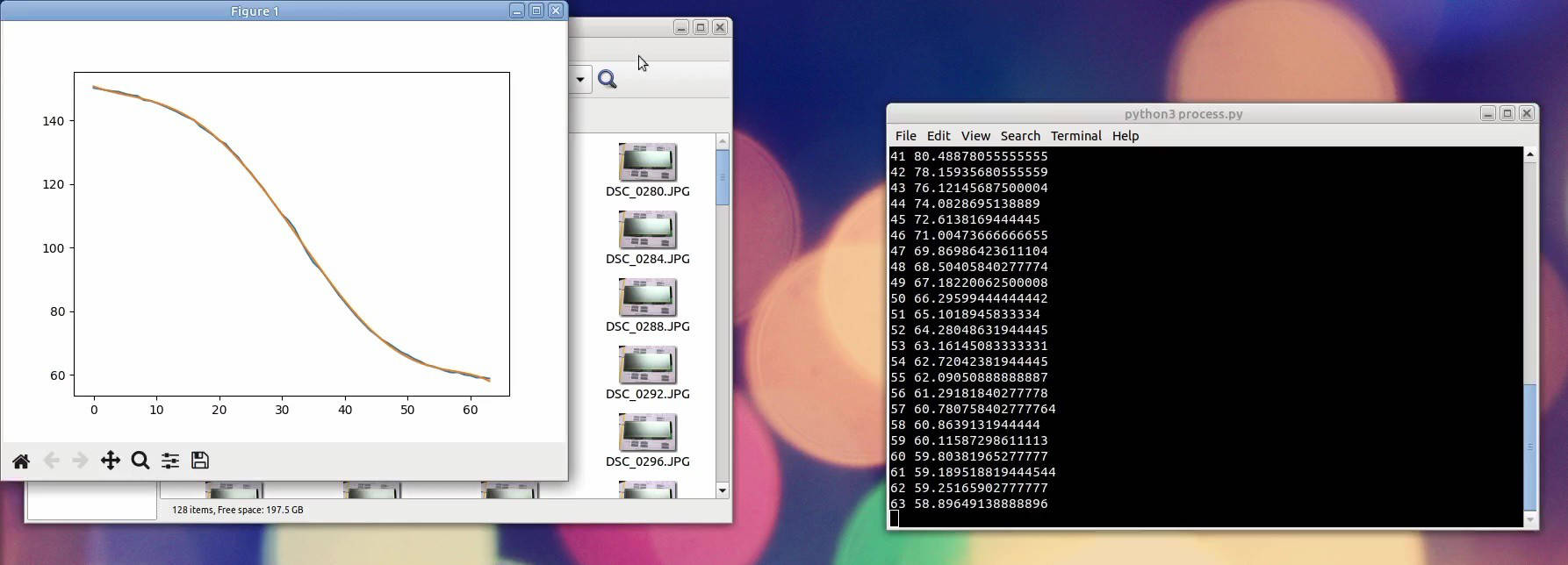
Cool, now the issue left is just the gamma correction, or grayscale calibration. As you could see, the screen response is quite non-linear, many levels near white and black are not usable. To get more usable levels, I am bumping up the total grayscale levels to 64.
Then I am letting it cycle through all 64 levels, and taking a photo of each level. I am using a simple Python script to crop the image to center and calculate the average sRGB value. If I plot this value against level number, the result is quite non-linear and matches the observation. The goal is to have a straight line here. Note this is not linear brightness, because displays should be tuned for a gamma of 1.8 or 2.2. But since the camera also does this gamma correction, I just need to shoot for linear sRGB value and the gamma should be automatically taken care of.
How am I going to do that? I cannot change the relation between output value and brightness level, but I can change how input is mapped to output. The input image is 256 shades, but output is 64 shades. I could just craft a table to map 256 shades into 64 and compensate for the non-linearity. Color LUT calibration on a monochrome LCD, did I go a bit too far?
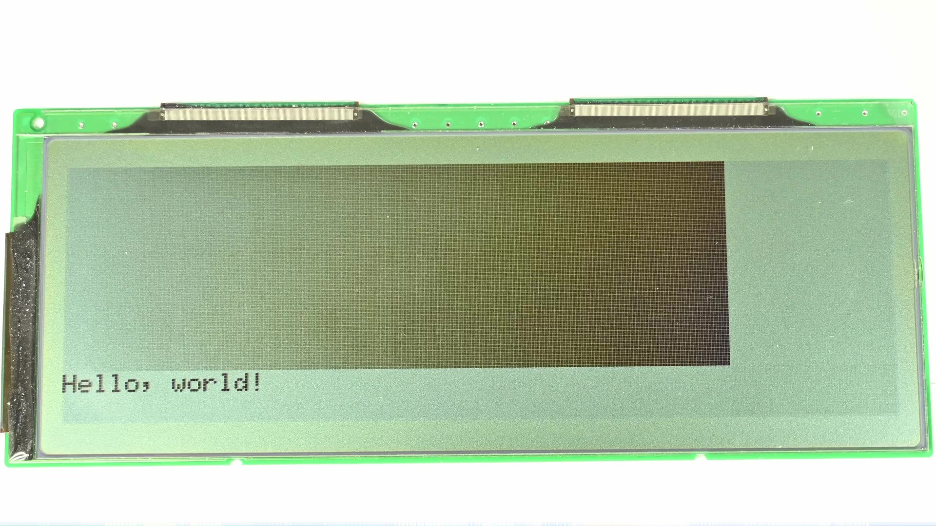
Now it looks really good.
To be honest, I didn’t come to this stage by accident, I have worked with delta-sigma modulators and noise shapers in audio applications before so I know these, and I have been wondering about if they could be applied to driving these LCDs for a long time. I looked through many different LCD controller manuals, searched many relevant papers, but it seems like no one is doing that. Finally I decided to just try myself and see if it would ever work. Now we can clearly see it works. But is it worth it?
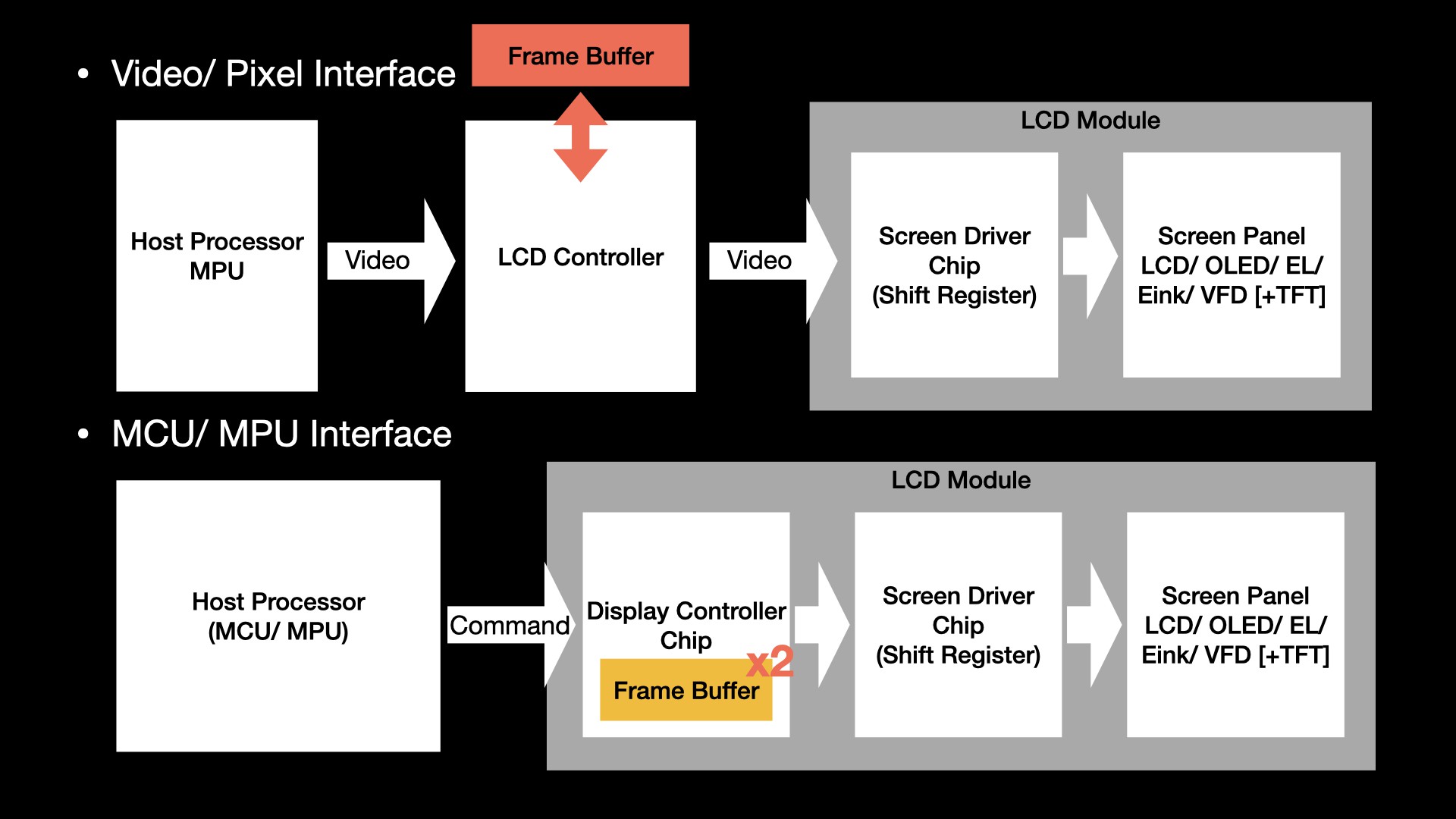
You see, in order to implement this feed-back loop, I had to create a state buffer for it to remember the accumulated error for each pixel. For the controller, the processing for each pixel is now a read-modify-write process to a large buffer compared to a table lookup. This additional complexity could mean a lot. In this proof-of-experiment I am using the microcontroller to emulate an LCD controller, but in real life applications, that would be an ASIC. If the LCD controller is originally like these self-refresh controllers, then it would need to double the size of internal RAM. But if the LCD controller is like those without memory at all, like a controller taking VGA input and outputs to the screen, this means it now needs to implement an external memory controller and a whole set of pipelines just for this.
So this could be why it’s never really being used. Instead people are using these pre-crafted sequences to drive the screen.
Okay enough about disadvantages, does it have any advantages? Let’s compare them. To ensure both sides have the same brightness response for the same level, I have reverted to using linear duty-cycle sequences plus the same calibration LUT.
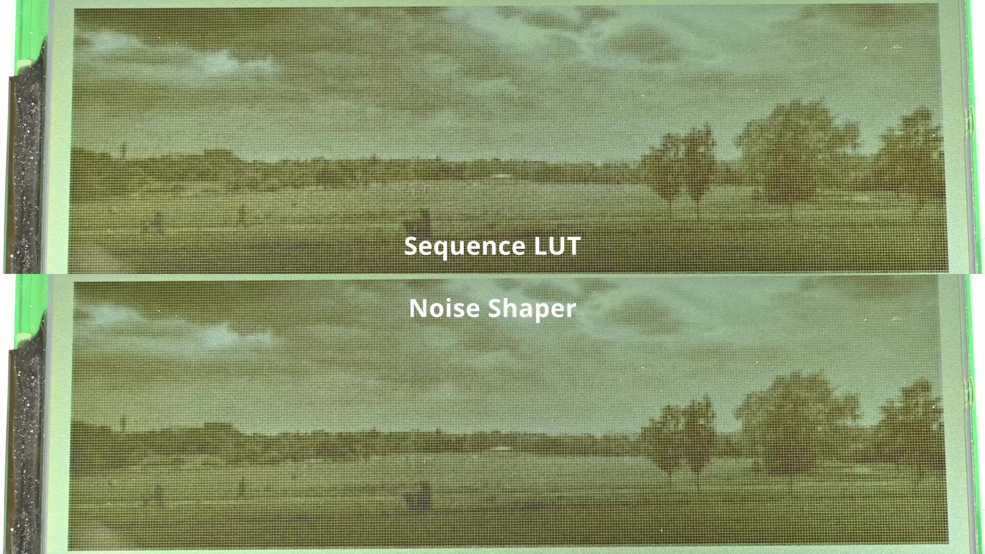
As we can see, with static images, there isn't much difference. In this test, using a noise-shaper doesn’t yield much meaningful advantage over the traditional approach.
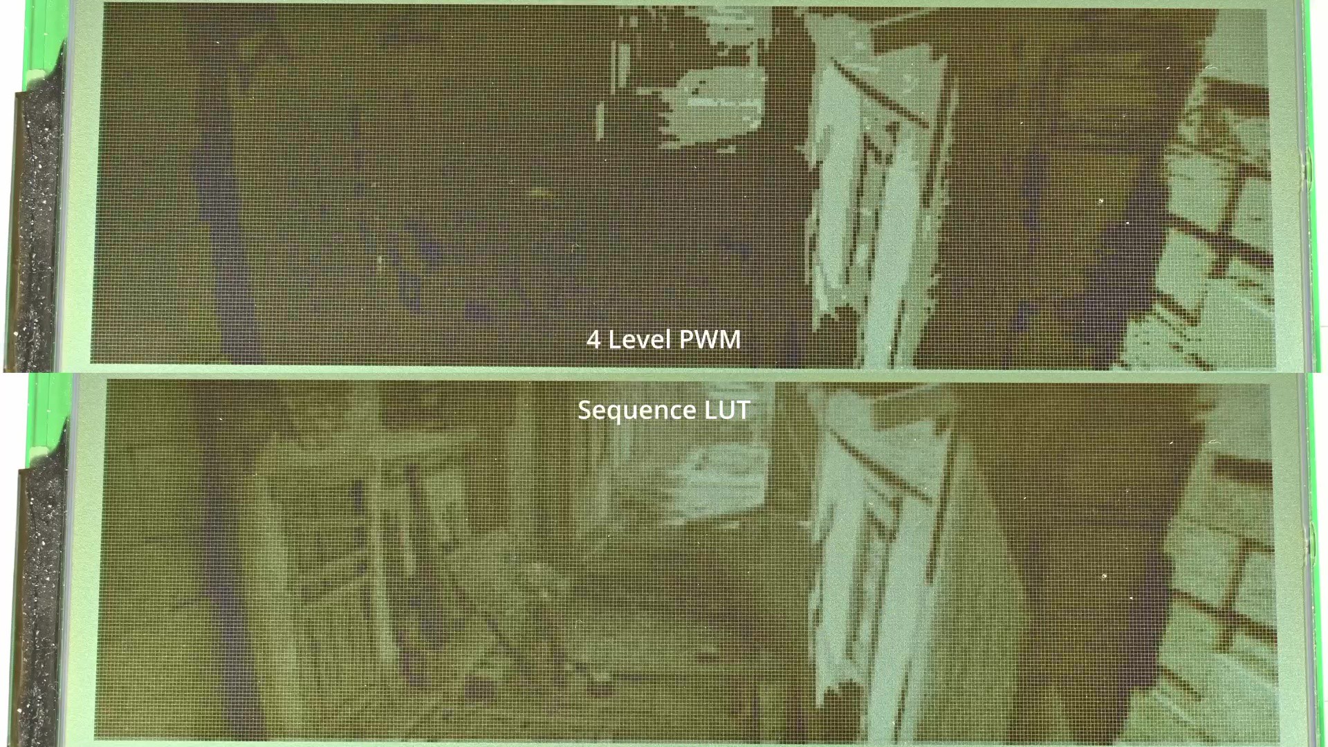
Now let’s look at dynamic response, or basically, playing back a video. The video I am using is the Sintel movie by Blender foundation, licensed under creative commons attribution 3.0. Just for the sake of fun, let’s first see the result with direct clamping, 1-bit spatial dithering, and the 4 level PWM grayscale.
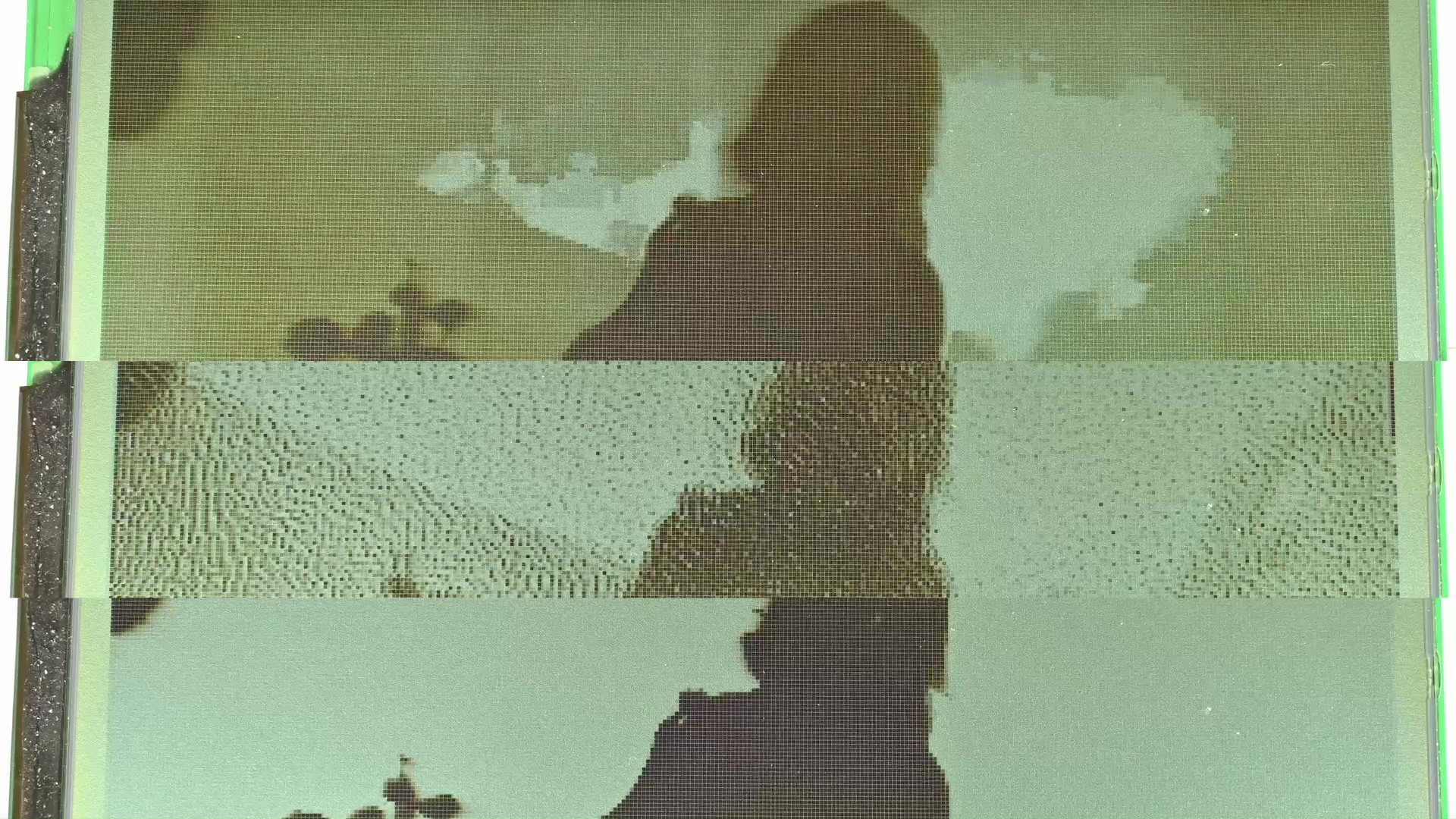
Well let’s bring in the kind of industrial standard method of using grayscale sequences. The video now looks much better right.
Then bring in the noise-shaper.
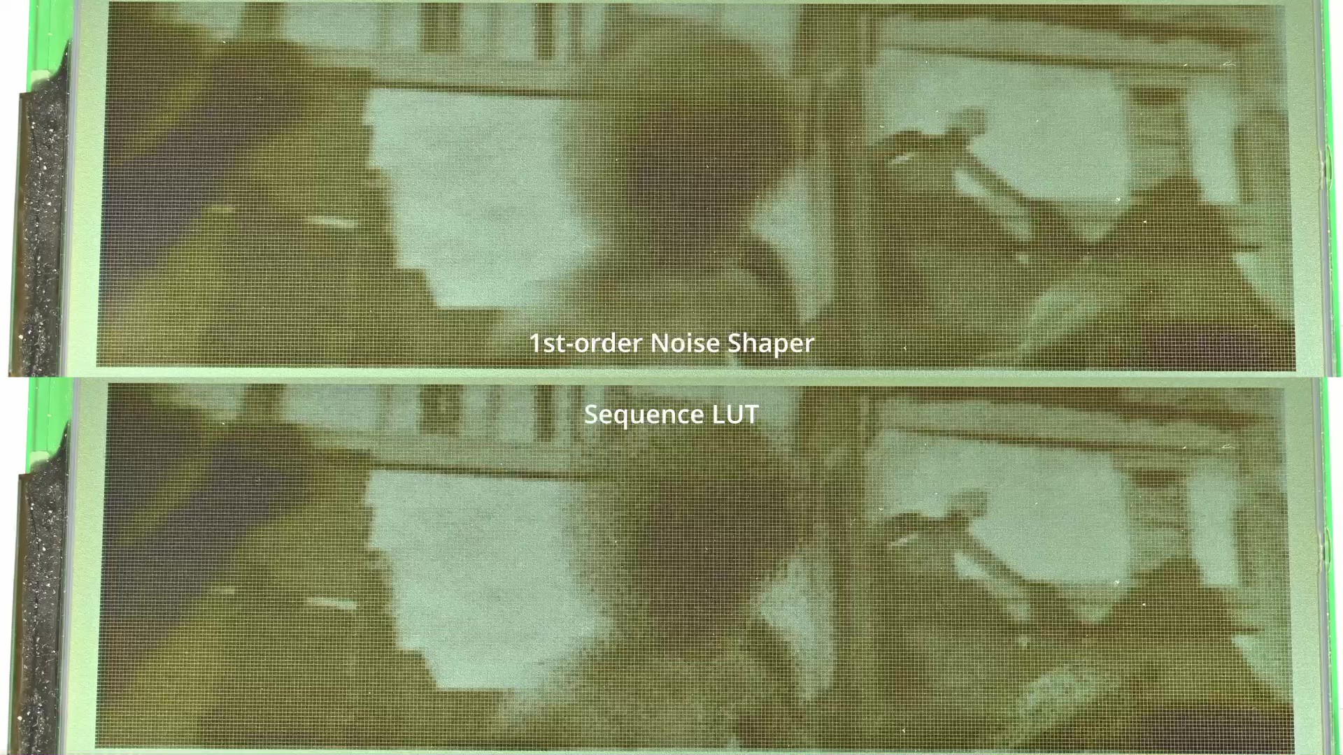
Now we could see the difference. With noise-shaper the dynamic response is much improved compared to using the pre-crafted sequence. Now let’s explore if this could be tweaked a bit more.
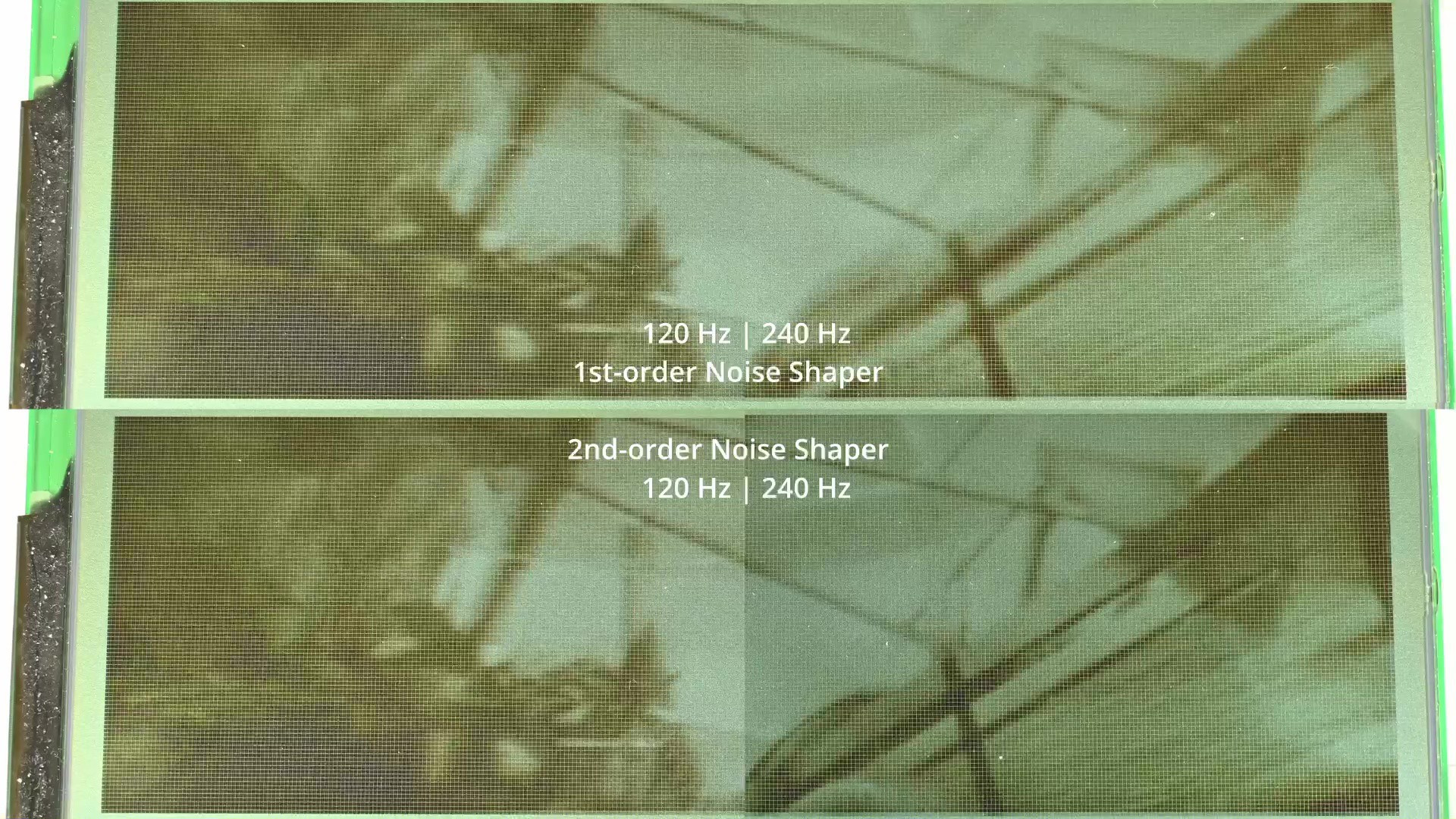
For example, currently this is a 1st-order noise shaper. What if I use a 2nd-order noise shaper? Well if we say the video frame rate is 24fps, and the screen is being refreshed at 120Hz, this is essentially an oversampling ratio of only 5. Given this low ratio, higher order noise shapers really struggle to improve anything. So, how about increasing that ratio?
I can overclock the screen to 240Hz, and see how it does now.
In conclusion, in this blog I explored and implemented various different methods of producing grayscale images on these passive matrix monochrome LCDs. In addition to use industrial standard methods, I have also tried using noise shaping technology commonly used in other applications here and got some fairly good results as well. That’s it for today, thanks for reading.