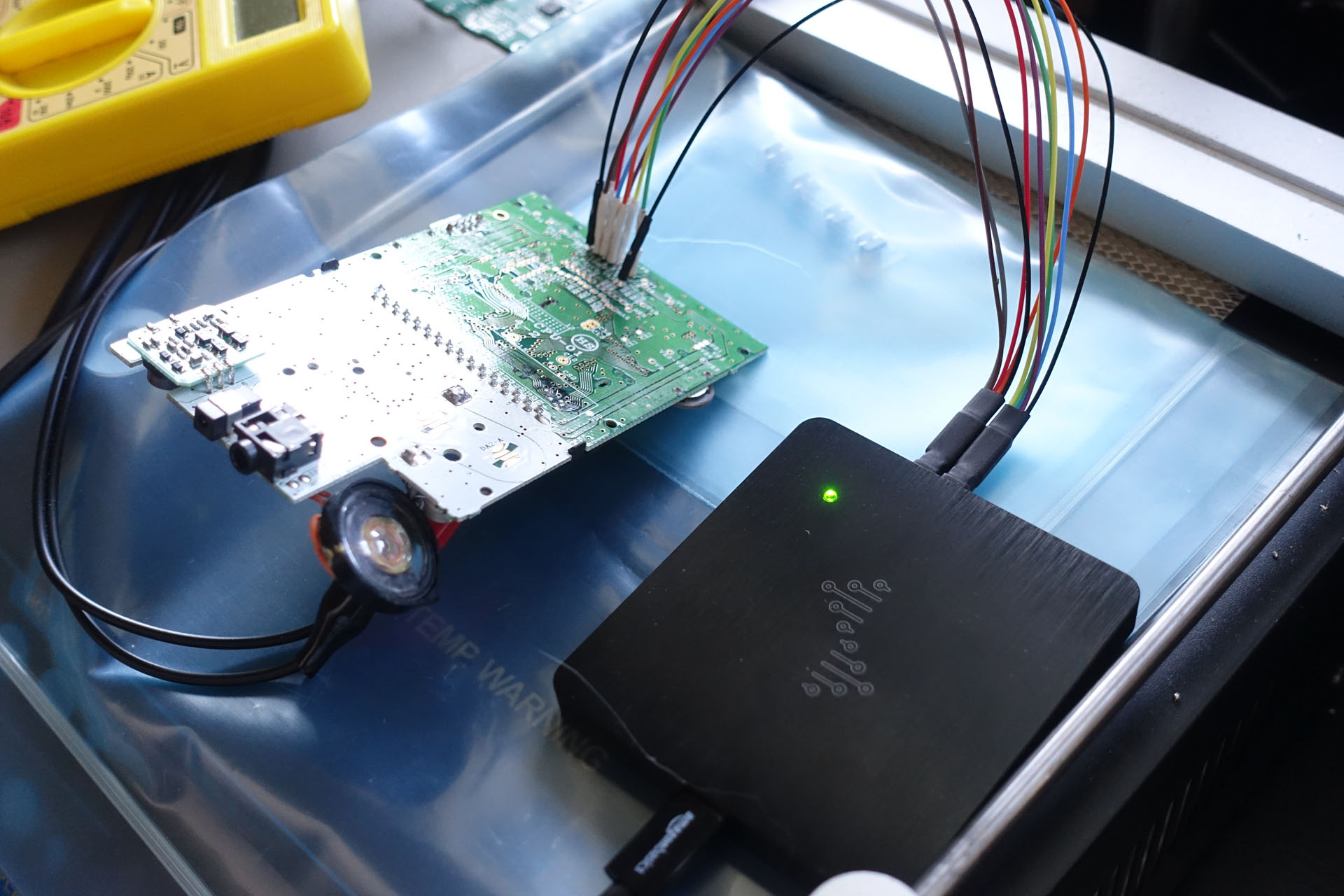
Because of the recent new project (RP), I finally have an opportunity to drive this screen. First about the difference of this screen and other screens I previously covered on this blog.
First of all, the screen is FSTN but uses negative high voltage. These themselves do not conflict, but generally speaking FSTN screen appeared later than STN, tend to use positive high voltage rather than negative high voltage.
Secondly, this screen has two different signals to control the horizontal sync, one called S and the other called CPL, but I am not sure about the difference.
Third, this screen has a signal called CPG, which pulses four times each line. The second pulse is immediately after the first, while the third and fourth are far apart. After testing the signal is related to PWM grayscale, such that adjusting the position of the third pulse would affect the depth of the lighter level of gray. It will become lighter in the forward direction, and darker in the backward direction. The fourth pulse is to control the depth of the deeper gray scale. If the position of the two pulses remains the same while the line length increases, the two gray levels will also fade.
For the refresh method, the MCU software refresh is used here. Current code can achieve a refresh rate of about 153Hz, so to save power there are about three options as follows.
- Baseline: MCU continuously refresh the screen
- Field standby: MCU update each frame after the WFI standby, maintaining a vertical refresh rate of 85Hz. The problem with this approach is that during MCU standby the screen also does not display content, which is equivalent to an increase in the duty cycle. In order to achieve the same brightness need to increase the drive voltage, which may bring additional power overhead.
- Line standby: WFI standby after the MCU brushes each line, maintaining a horizontal refresh rate of 13.6kHz and a vertical refresh rate of 85Hz.
The test results under the current hardware are as follows.
- Baseline: 125mW
- Frame standby: 117mW
- Line standby: 106mW
Basic Information
- Type: Monochrome Dot-matrix STN
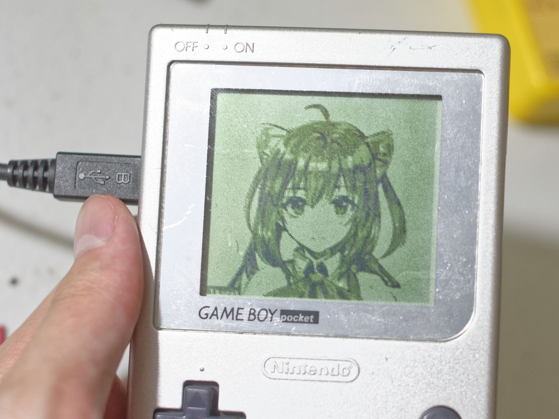
- Mode: FSTN Reflective
- Resolution: 160x144
- Greyscale: 2bpp
- Driver: Unknown
- Size: 2.6"
- Backlight: None
Pinout
- GND
- CPG
- CPL
- ST
- D0
- D1
- CP
- FR
- V5
- V3
- V2
- CPL
- S
- VDD
- FR
- V1
- V4
- V5
Typicall VDD is 5V, but 3.3V could also work. Optimal V5 is between -12V and -17V. Maximum CP frequency is around 8 MHz.