Hello everyone, it has been a while. This video I would like to share one of the projects I finished recently, ELterm. Which stands for electroluminescence terminal. I bought these Planar 640 by 480 electroluminescence screens a few months back. The display is sort of similar to OLED, but it’s monochrome. These dot matrix screens typically emit yellow or amber ish color, but there are also models which are red and green dual color. Naturally I want to make something with this screen, and I decided to make a serial terminal with it, so let’s get started.
First is about the processor selection. I would like to implement the whole thing with just a microcontroller. The serial terminal part should be okay, the original VT220 was based on a microcontroller anyway. But refreshing the screen might not. Most of the dot matrix display technology requires constant refreshing, like at 60Hz. Screen modules that’s commonly used with microcontrollers are self-refresh screens. The screen module has its own memory and controller, and would refresh from its own memory without microcontroller intervention. For example, like these OLED modules, while the OLED needs constant refreshing, I could just disconnect the microcontroller, and it keeps the display. There exists self-refreshing EL screens, but the one I have isn’t. It demands to be refreshed at 120Hz, which means the microcontroller needs to continuously push data to the screen at 120Hz.
This put some requirements on the microcontroller. It would either hold the entire framebuffer in the RAM, or it could generate image data at screen refreshing speed. Both works, but bing able to store the frame buffer would be a bit more flexible. Then it should be able to generate the timing needed by the screen. Obviously one could do this with an FPGA, and I do have an FPGA video coming up in the future, but that’s for another time. For this time, many of the 32bit microcontroller works here, I chose the RP2040 from Raspberry Pi.
Here are the main spec for the RP2040. Dual-core Cortex-M0, 264KB SRAM, no internal Flash, executes code from SPI flash. The most important part for this project is it has PIO, which is a micro-code programmable IO module. I will show how to use it to drive the screen.
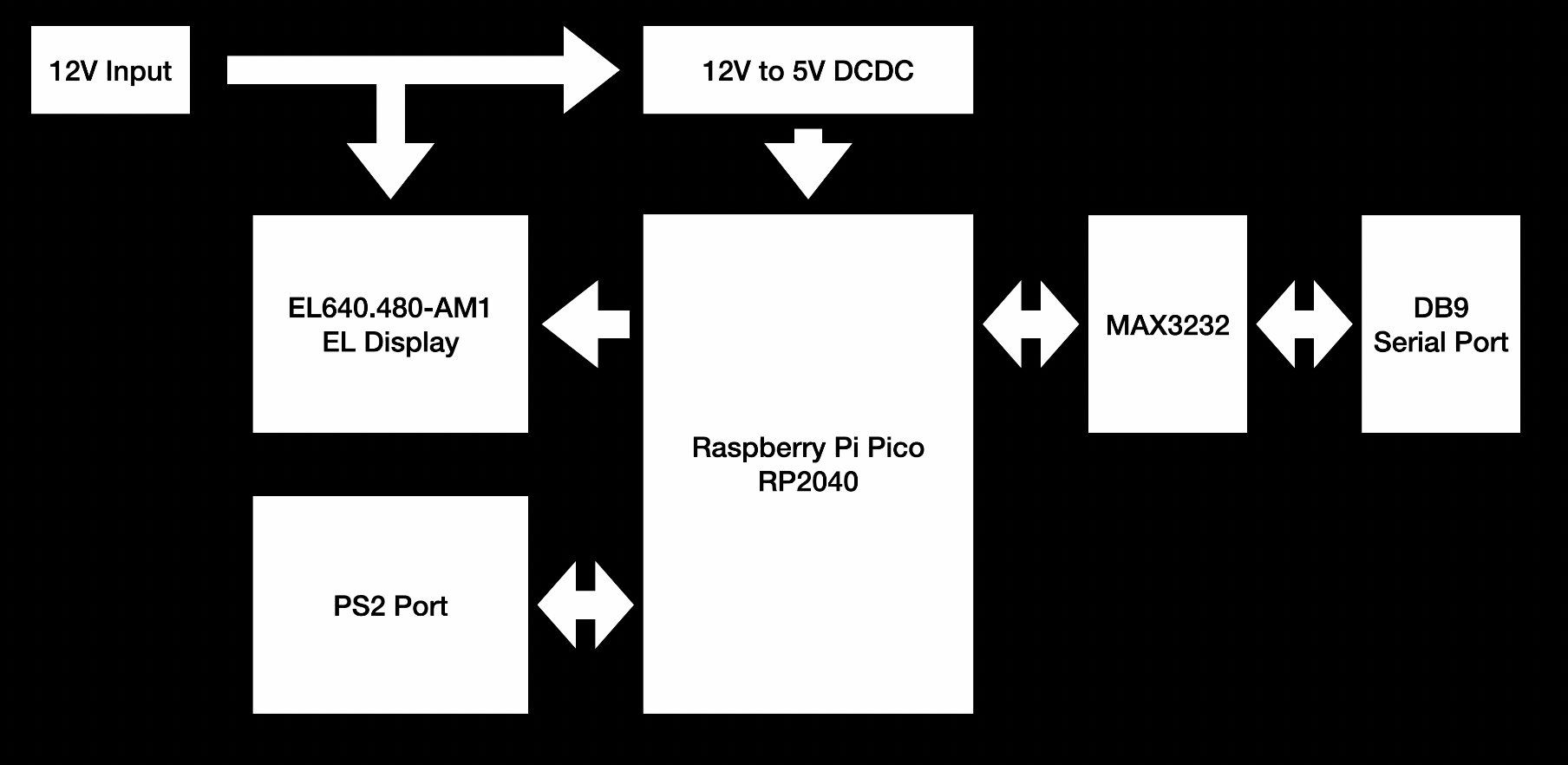
Now let’s take a look at the overall design. With the microcontroller in, I just need to fill in the interfaces I need. The screen doesn’t need any extra interface chips, and could be connected directly to the microcontroller. The terminal needs keyboard input, so adding a PS2 port here. Of course I could also just use the USB port of RP2040 itself. At last, the terminal needs a serial port, so adding a MAX3232 for a RS232 port, with jumpers for TTL serial options. For the power supply, the screen has internal high voltage generation, so only a 12V is needed. I decided to use 12V input for the whole board, and then use a 12V to 5V DCDC to power the Raspberry Pi Pico.
Then comes routing the board. To keep things simple, I am using the Pico as a module and mounting it directly on the board. There isn't much special about this board. So I am not going into details.

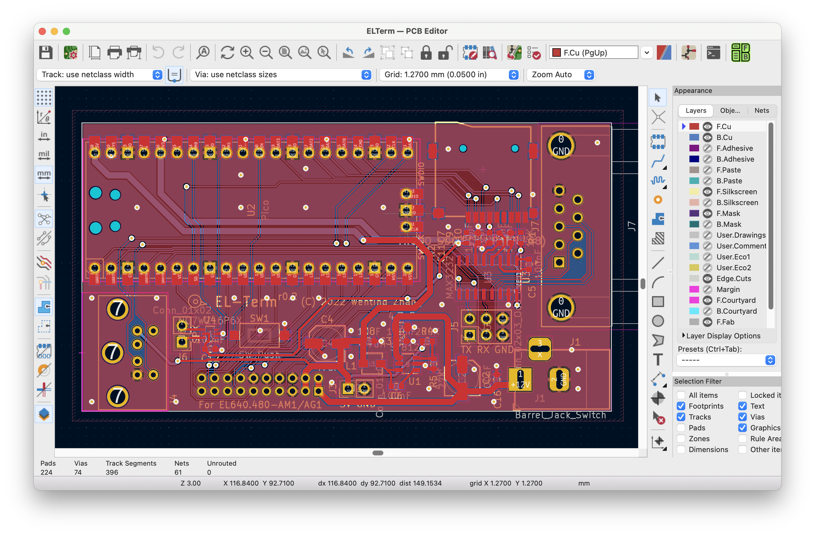
Once done, exporting the Gerber, submitting to the manufacturer, and a few days later I got the board. Then soldering the board. I usually solder the capacitors and resistors first, then chips, and last the connectors. There isn't much stuff on this board, and to be honest, I have been mostly working on more complex boards like with FPGA or SoC or DDR, and it’s refreshing to work with these simple 2-layer microcontroller boards again.
Now it’s time for coding. Screen driving related parts have been detailed in a previous blog post, so I am going to skip this part.
The next step is implementing the serial terminal. It might sound easy, which is basically displaying whatever received from the serial port, and sending out whatever user typed to the serial port. So let’s do it. Prepare a suitable dot matrix font, write code for displaying the text, building a software FIFO for buffering data received in the serial interrupt and fetched in the main loop. Keyboard wise, RP2040 SDK has built in support for USB keyboards using the TinyUSB library, so it’s just a matter of translating the keycode into ascii and sending them. Easy enough right.
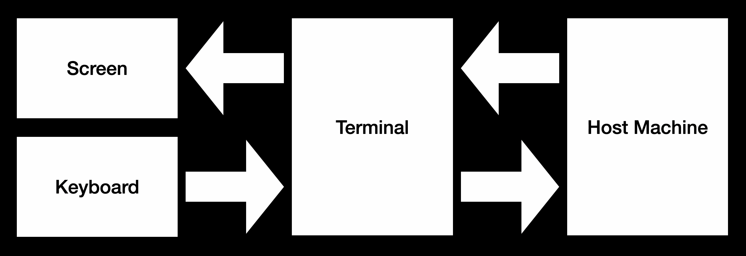
Unfortunately no. Obvious issues, there is no arrow key, function key, or paging keys in the ASCII. How do I send these? Then, typically the host needs to send more than just texts to the terminal. It also needs to tell the terminal where to put the text, what color the text should have, etc. All these are implemented with escape sequences. For example, to move the cursor to position 2,4, one could use a sequence like this to implement. Host just needs to send this sequence, and the terminal should parse and do the corresponding task.
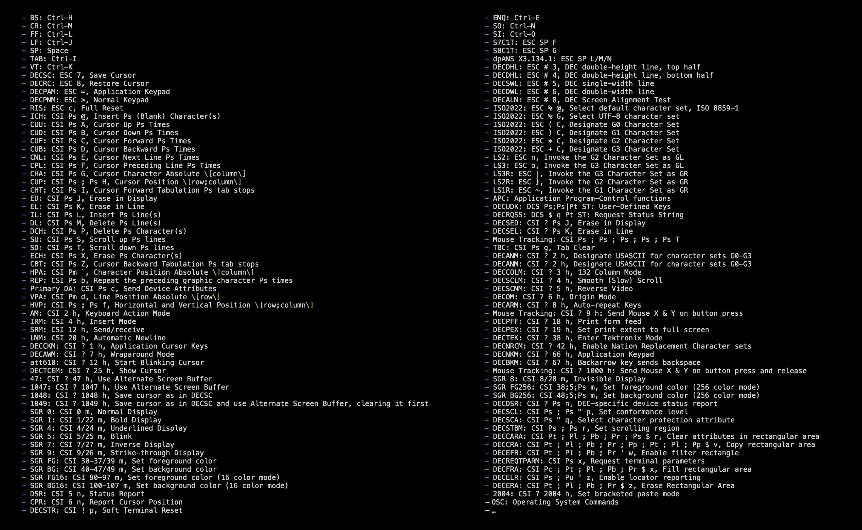
There are lot of such sequences. I selected and implemented a few supported by xterm. Which also implies there are tons more I didn’t support. Plus there are even more subtle behavior differences between terminal standards, which could be quite daunting to figure out and implement correctly.
For example, imagine the host keeps spitting out texts, until one line has been filled up. If it keeps printing, then the text would go to the next line by default. But where should the cursor be by the time it has just been filled up? What if the application requests to move the cursor at this time? Does that happen before moving to the next line, or after?
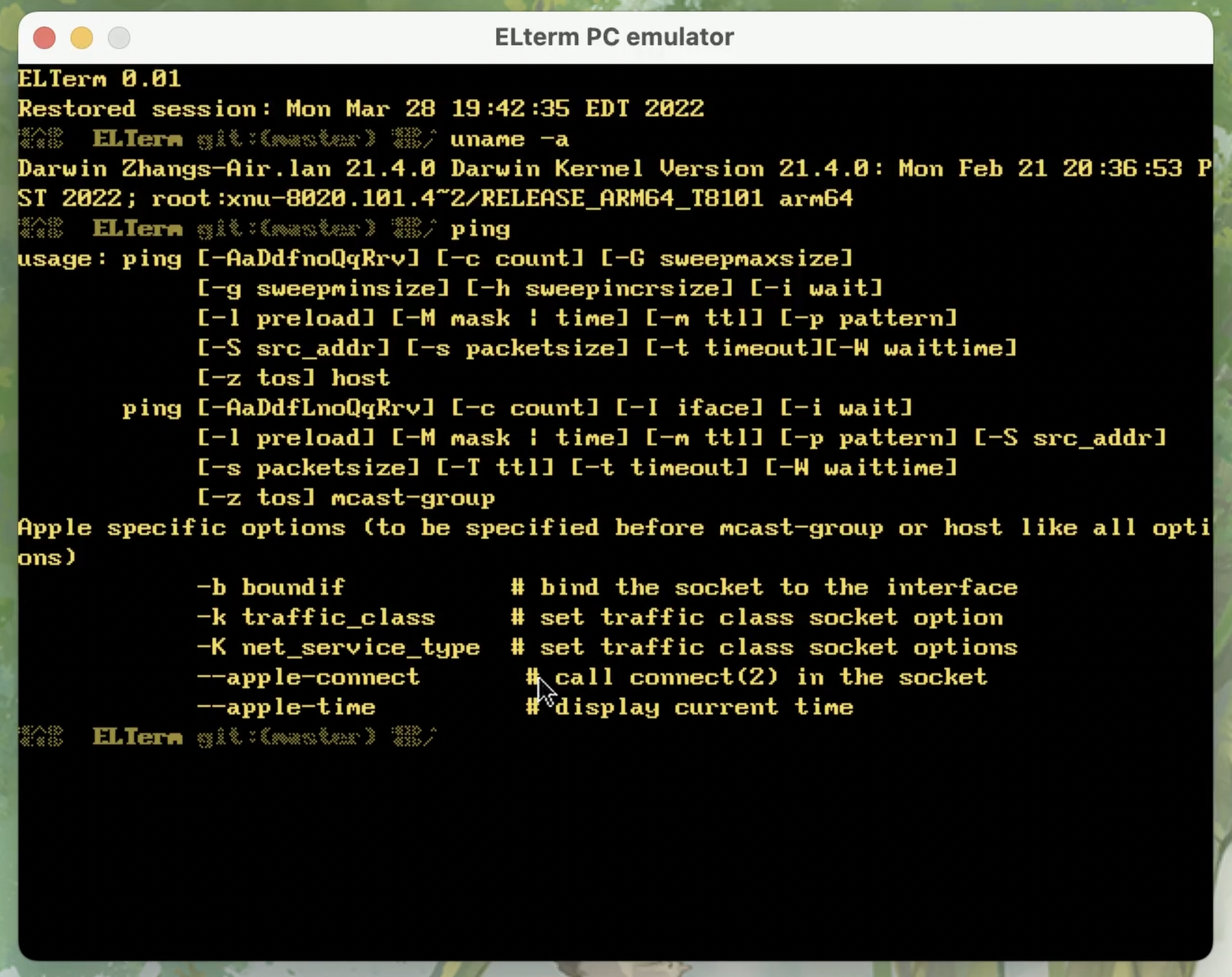
To help with debugging and testing, I ended up porting the entire firmware onto Linux and macOS, so it functions as a terminal emulator. In conclusion, if one is looking to build a usable terminal, I will still suggest looking into existing libraries, such as libtmt or libtsm. But otherwise, it could be fun to start from scratch.
Now let’s run it and see it in action. I am connecting it directly to the Raspberry Pi:
Like running ping, or running htop
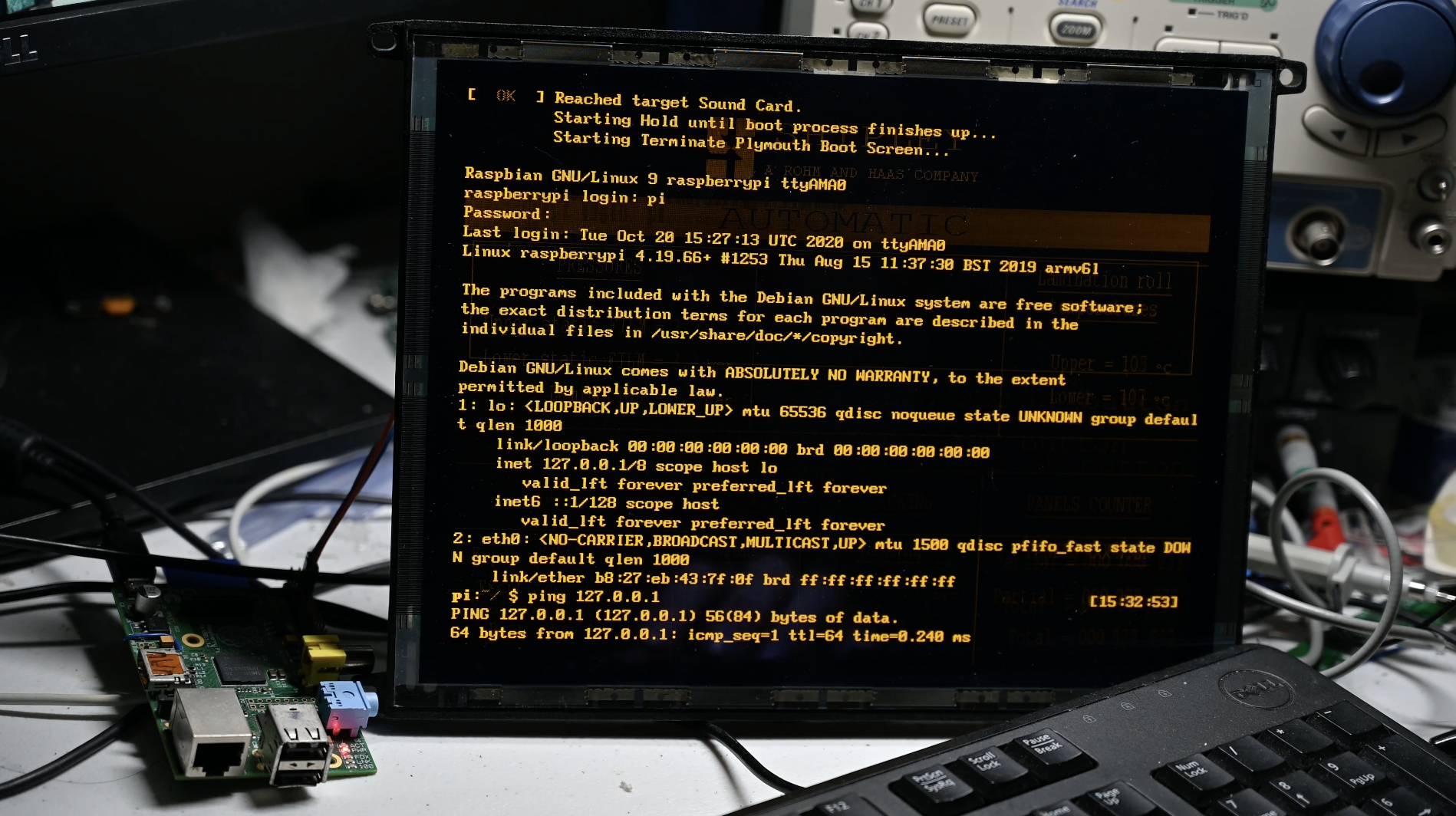
It’s a serial terminal, so there is no graphical display
This is about the end, thanks for reading. See you next time.