Introduction
Back in the last century, when the CRT was still the most common technology for computer monitors. It was quite common to see such an argument: the LCD will probably evolve and produce better images, but it is never going to replace the CRTs. CRTs are just objectively way superior in terms of image quality, and LCDs are only suitable for applications requires absolute low profile and low power consumption[1]. Several decades later, we all know what happened in the end. I think it was be fun to take a look at the LCDs at that time, are they really that bad? What it would be like to use that kind of screen in 2019?
LCDs in the last century
There were several different types of display being used on portable PCs last century. The very first portable PC in the last century usually comes with CRT displays, like Compaq Portable (1983) or IBM 5155 (1984). Of course, it is clear that CRTs just too heavy to be used on these portable devices. Later they switch to TN LCDs, like on IBM 5140 (1986) and Toshiba T1000 (1987). These TN displays has very low contrast and very poor viewing angles.
Later some companies experimented other technologies like Gas Plasma screens on Toshiba T3200 (1987) or IBM PS/2 P70 (1991). Gas Plasma screens provides perfect contrast, but the color was limited to different shades of orange, and was very expensive to produce.
Finally, in the early 90s, the industry switched to the STN LCD screens. These STN screens provided not too bad contrast (typically 1:5 to 1:50), and few shades of gray. Given these laptops are mainly for business uses, STN screens was good enough. But what if one want color display? There were two choices, CSTN and Color TFT. The first laptop with a color TFT screen was the NEC PC9801NC, came out in 1990. The TFT screen provided much higher contrast ratio and much lower response time, with one drawback: it was expensive to manufacture. CSTN, on the other hand, was basically a STN screen plus a color filter. Cheap to manufacture but the performance was limited. As a result, STN and CSTN continues to dominate the market, and being used widely on low-end laptops. Today we can still see CSTN screens being used on New York subway trains.
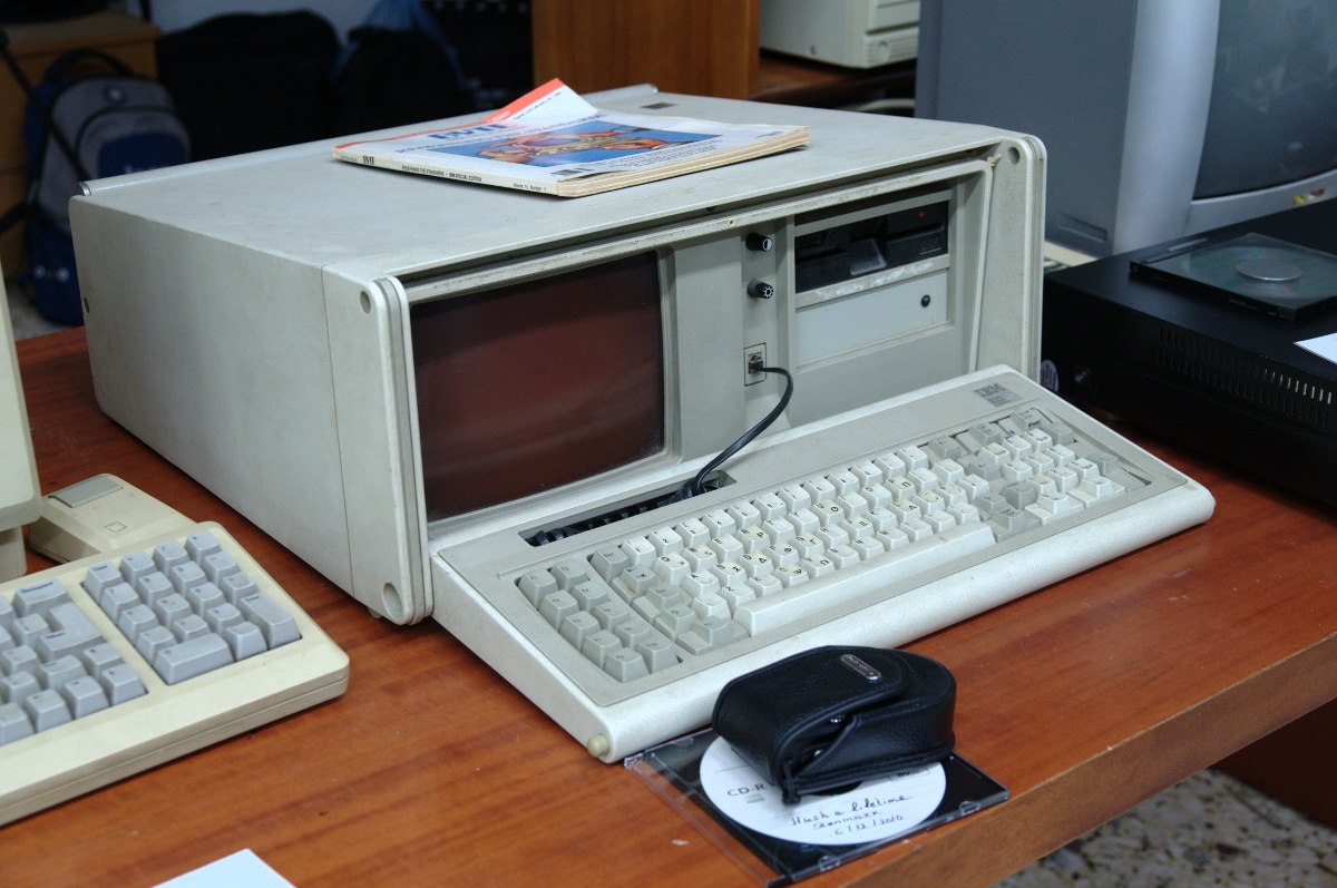
(IBM 5155, credit: Soupmeister, license: CC-BY-SA-2.0, source: https://www.flickr.com/photos/29012094@N07/5235790747)
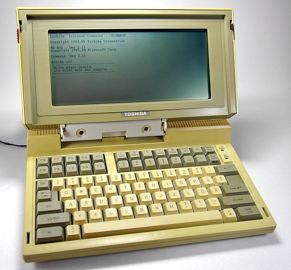
(Toshiba T1100 featuring a monochrome TN screen, credit: Johann H. Addicks, license: GFDL, source: http://www.addicks.net/gallery/Irgendwo/Toshiba_T1100_In_Betrieb)
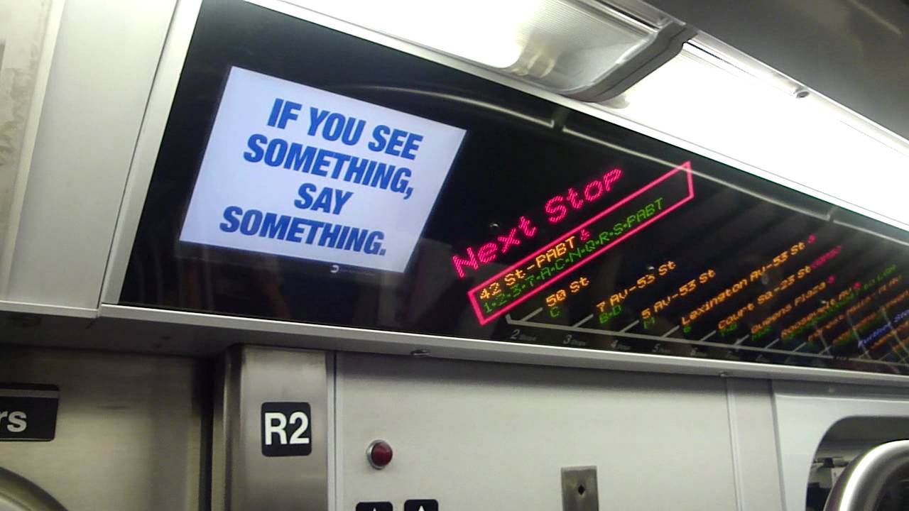
(This screen on MTA trains is a CSTN screen. Credit: Transit +PLUS)
As you have already know from the title, this project focus on the CSTN screen, leave out early TFTs, monochrome TN, and monochrome STN screens.
The CSTroN
I have determined that I want to take a look at CSTN screens. The next question is how. Surely it is not hard to find a laptop with CSTN screen, and by just using that laptop I can get an idea what it is like to use a CSTN screen. So, I got myself a laptop from last century, powered by a AMD 5x86-P133 processor. Given the performance it has, things I can test are basically limited to DOS games. Surely there are many amazing DOS games out there, and I enjoyed playing them on that laptop. I wish to play some modern 3D games and watch YouTube videos on that screen and see how it behaves, but it is simply impossible.
Or is it?
The laptop limited what I can display on that screen, so I just need to get rid of that laptop, leave only the screen. I can then try to add a standard VGA or even HDMI port to that screen, and hook up whatever modern device I may want to.
Actually it is a pretty common hack to mod a laptop screen into a VGA/HDMI monitor. The usual way of doing that is just buying a LCD driver board that match the screen, and hook the screen to the board. These driver boards are widely available on places like eBay and AliExpress. One may also drive the LCD themselves with an FPGA: you decode the HDMI or VGA using a decoder chip into a pixel stream, you transmit the screen through LVDS to the screen, done.
Now what’s my situation? Well, it seems like VGA CSTN LCD driver boards was a thing decades ago, but they are hard to find nowadays. Leaves the FPGA my only choice. Fine, I will do it with my beloved ML505 FPGA development board.
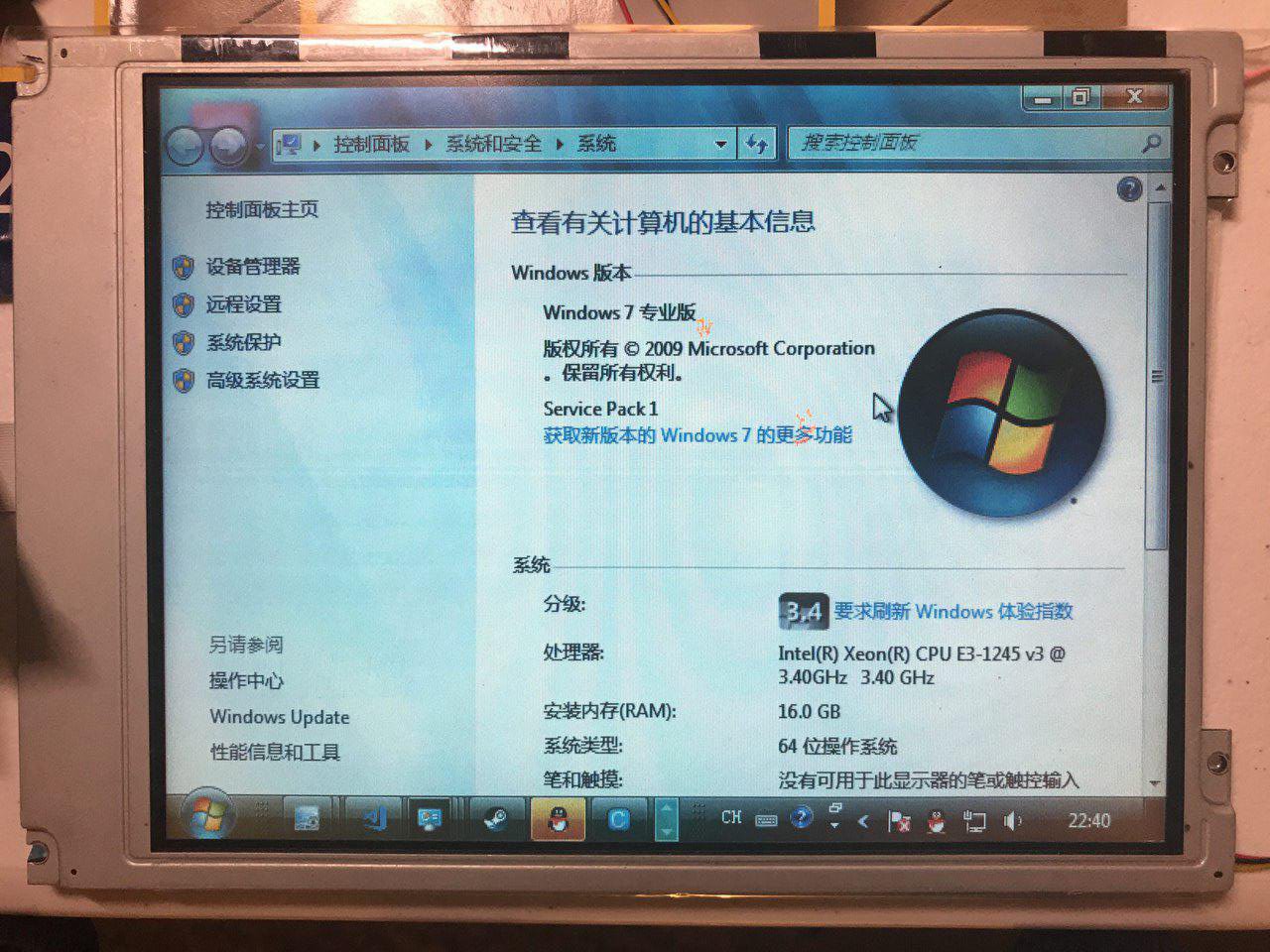
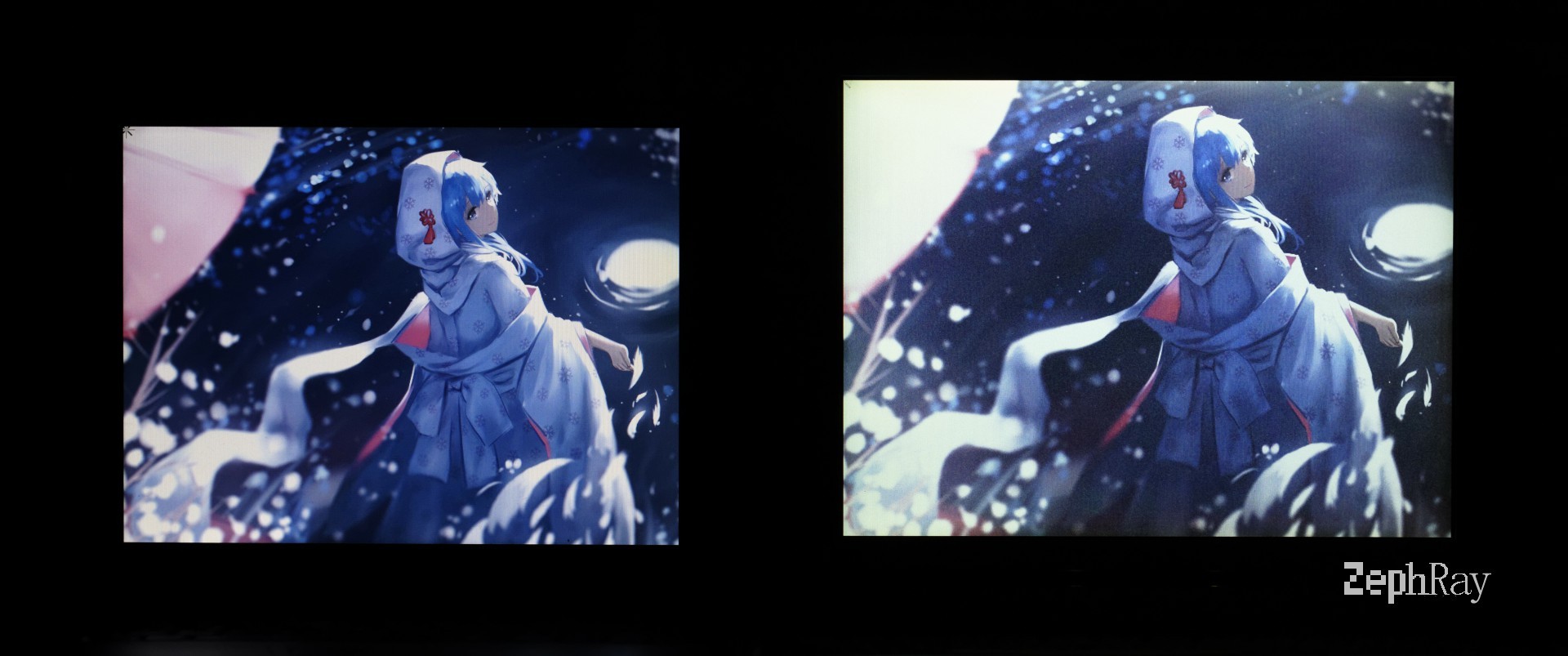
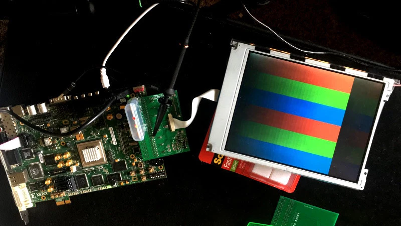
(The finished CSTroN, displaying system property. Of course this is probably something you would never normally see on a CSTN screen.)
Driving the CSTN
Let’s talk about some basics of CSTN screens. Like all other matrix displays, pixels are organized in a row and column matrix. By applying the correct AC voltage on both selected row/ column and deselected row/ column, one can control the state of every single pixel, and up to one line at a time. By outputting the image line by line, refreshing the whole screen at a high refresh rate, the image is generated. Basically all dot matrix screens works like this. If you have written driver for small LED matrix display on micro-controller, you should understand how it works. The LCDs are just more complicated to deal with, as they require an AC voltage rather than DC. Another implication of AC is that, for sure reversed current could also turn on the pixel (unlike in the case of LED), so the driving voltage should be biased, making pixels should turn on have a higher Vrms, and pixels shouldn’t turn on have a lower Vrms.
Luckily, I don’t need to handle these biased AC voltage stuff. They will be handled by the display module (A switching power regulator would generate the high DC voltage for driving. The DC voltage go through series voltage dividers and then buffered by a voltage follower, generating the biased DC voltage. These voltages goes into the row and column driver, based on the input pixel data, modulated into correct AC waveform and drive the LCD.). What I need to care is just the pixel data that need to feed into the display module.
On a common DPI TFT LCD, pixel data are sent through the data bus one pixel a clock. Two dedicated wire called horizontal sync and vertical sync would pulse on the end of a line and on the end of a frame. The pixels are just like this written into the LCD continuously. Usually the pixel clock frequency is picked such that it takes 1/60s to transmit a full frame, so the refresh rate would be 60Hz. The width of the data bus would just be the color depth of the LCD panel. Common values are 16 bit (for RGB565), 18 bit (for RGB666), or 24 bit (for RGB888). DPI interface are the basis for all the TFT LCD interfaces, LVDS is just a serialized DPI transmitted over LVDS differential pairs, and MIPI DSI is just DPI encapsulate into packets and transmitted over MIPI DSI bus. For the SPI/ i80 bus LCDs, they have an integrated controller chip, that would receive the command from host controller, and generate the DPI or DPI-like signal internally to drive the row and column drivers. You may notice this is very similar to the VGA signal, except the analog RGB signals has been replaced with digital RGB signals. This making converting between these two signals very simple: use a DAC to convert from DPI to VGA, and use an ADC to convert from VGA to DPI. This is basically how Raspberry Pi’s VGA expansion board works.
CSTN’s signal, at first glance, is very similar to that of TFT (taken from SX21V001 datasheet[2], it is a 640RGB480 CSTN screen):
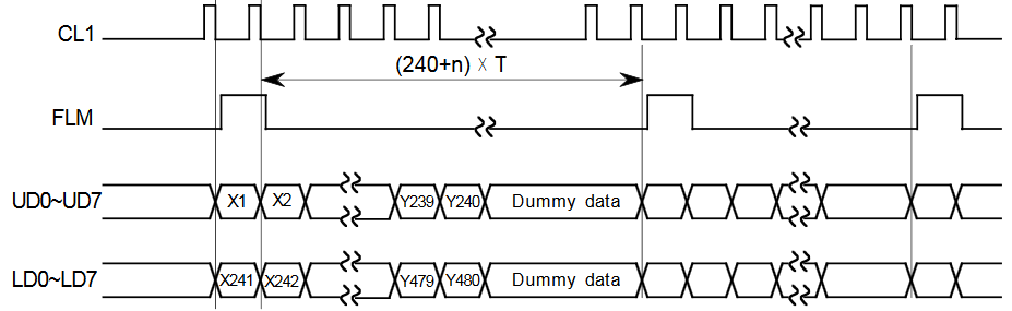
This is when viewing in the scale of a whole frame. The CL1 is pulsed every line, meaning it works like a horizontal sync signal. The FLM is pulsed every frame, meaning it works like a vertical sync signal. And there are 16 data lines… There is one obviously error in the diagram, during first line and second line, UD0-UD7 sends out Y1 and Y2 instead or X1 and X2, and LD0 and LD7 sends out Y241 and Y242. So here we can see, 16 data lines, instead of sending out one pixel together, are used to separately transmit pixel data for upper and lower screen. This makes the screen actually looks like two 640*240 screen concatenated together from the host perspective. They did this due to the limitation of the biased voltage addressing method all STN screens has to use: the contrast ratio is inversely related to the row numbers (the vertical resolution goes up will cause the contrast ratio goes down). By dividing the upper and lower screen, the effective row number cuts half, improving the contrast ratio. But this not the only oddity CSTN/ STNs have compared to TFT LCD:
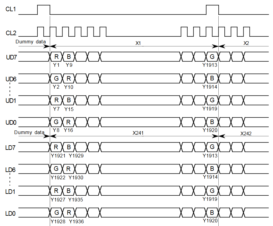
I am not sure why they are referring horizontal axis as Y here… But anyway, here CL2 works like a pixel clock. But UD and LD buses, instead of outputting 1 pixel per clock, with different all bits used to represent an unsigned integer of brightness, each bit represent a pixel. This means each pixel can be either on or off, but not any intermediate value. 1 bit for each sub-pixel (1 bpc, bit-per-channel), gives us 3 bpp (bit-per-pixel) color depth (8-colors).
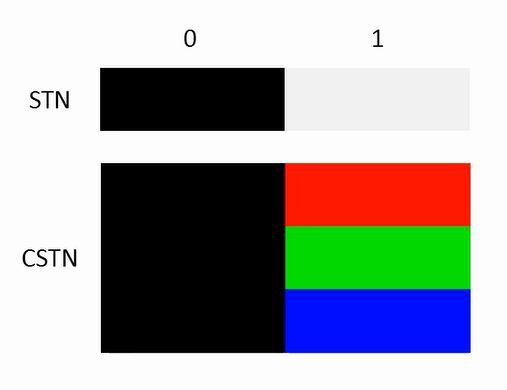
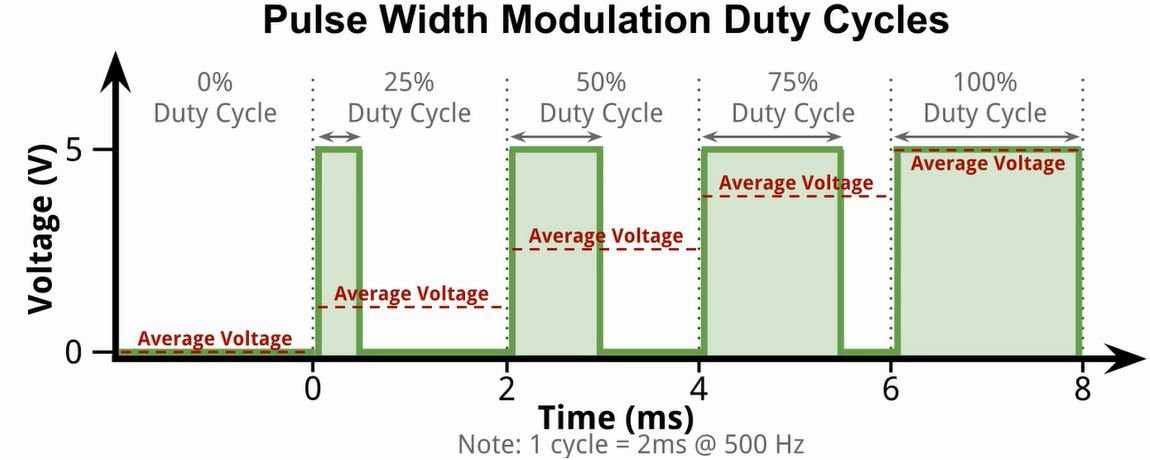
But wait… We know that CSTN has poor color depth, usually like 4096 colors or 32768 colors, definitely not 8 colors! Well, the screen driver could only support up to 8 colors, but there are still something we can do: PWM. PWM is a common way to dim a LED, it can also be used to dim the LCD here. For example, to display a 50% gray, you simply alternate the pixel on and off between frames. Usually, this technique is called FRC, term PWM is referring to the technique of alternate the pixel within one frame. FRC is implemented inside the LCD controller, while PWM is implemented inside the LCD driver (means it need to be supported by the LCD module). I am currently not aware of any CSTN LCDs that support PWM (I suspect some later HPA-type CSTN LCDs support PWM, but I am unable to find datasheets for them). But any way, this is the way to support higher color depth. 4 bpc gives 4096 colors and 5 bpc gives 32768 colors.
Of course, FRC doesn’t gives you more color just for free, this method is subject to flickering. Generally higher refresh rate is required to compensate this. The LCD I am using has a typical refresh rate of 120Hz, and I overclocked it to 240Hz.
Implementation
Given the odd driving requirement CSTN has, here are the few challenges:
- The input video signal has a refresh rate of 60Hz. The output video refresh rate should be at least 120Hz.
- The input video signal is a single scan pixel stream (pixels from top left to bottom right). The output video is a dual scan pixel stream (pixels from top left to middle right, and from middle left to bottom right, concurrently).
- The controller should have an FRC implementation to display image with higher depth than the native depth of the panel.
The first two challenges basically means the output stream can never be fully in sync with input stream. A frame buffer is a must in this design. Input stream and output stream will write to and read from different places at the same time.
For the third challenge, I will use something called GLDP LUT: Grayscale-Level Display Pattern Lookup Table as described in [3]. Basically, it is a look up table with two inputs: the color need to be displayed (signal width is related to color depth, for example 4 bpc means this signal needs to be 4 bits wide.), and the current frame counter. It produces one output: the pixel data should be sent to the display. Its width should match the display’s native color depth, here it should be 1 bit.
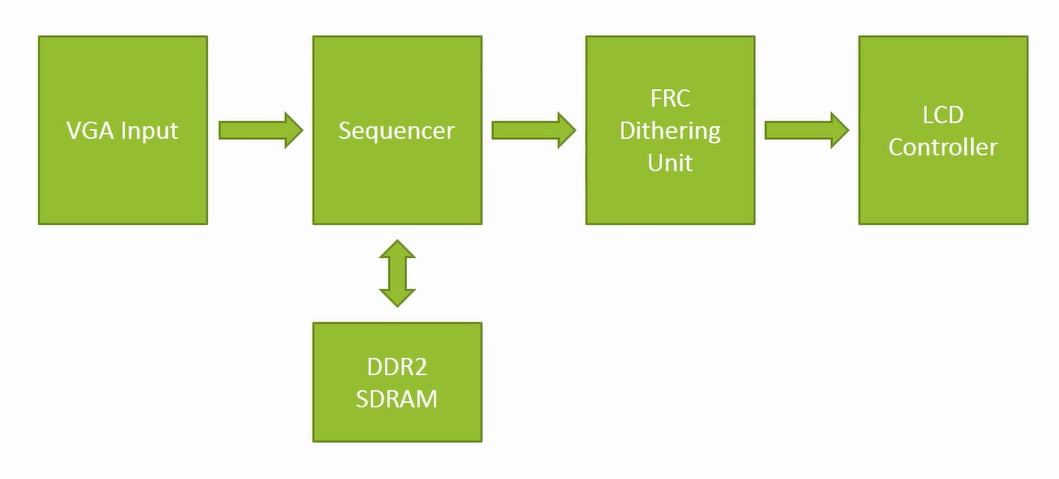
Here is the planned architecture:
Anyway, for the implementation, the first step is always just display some pure color. This can be done fairly easily, since one don’t actually need to worry too much about all the oddities it may have: all the pixels just display the same color, it doesn’t matter where the pixel actually is, the main goal here is just write a module that will generate the correct waveform. You may find the final version of the driver module here: https://github.com/zephray/CSTroN/blob/master/rtl/lcdc.v.
After the basic tests passed, we can start working on the gray-scale display. It is mostly a trial-and-error process, trying to produce a LUT with minimal visible flickering. I finally used two different but equivalent LUTs, applied to the screen in a checkerboard pattern, means none of the neighboring pixel would use the same LUT. This could greatly minimize the visible flickering. You may find the GLDP LUT here: https://github.com/zephray/CSTroN/blob/master/rtl/gldp_lut.v
Now all the displaying part is done, next step would be implement the frame buffer. For a 640*480 RGB555 framebuffer, the size is around 600KB. Not a very big number, but definitely bigger than my FPGA’s internal memory capacity. The on-board DDR2 memory is used in this design. Xilinx MIG is used as the DDR2 controller. There are two FIFOs in the design, one is the read FIFO, and another is the write FIFO. One arbiter would decide if the next DDR transaction would be read or write. Dual buffering is also utilized, the incoming stream would always write to the back buffer, and the output stream would always read from the front back. When an input frame is completed, front and back buffer are swapped. The finished arbiter code is here: https://github.com/zephray/CSTroN/blob/master/rtl/sequencer.v.
Finally, things left is the video input. I reused the same code from my previous project, basically it is just a video ADC, converting the VGA signal into DPI signal. The code can be found at: https://github.com/zephray/CSTroN/blob/master/rtl/vga_input.v
Conclusion
A simple demo can be found here: Youtube or here: Bilibili
As my third FPGA based project, it was fun to implement and rewarding to see everything working. I got to play around with the Xilinx MIG and DDR2 memory, as well as some rudimentary pipe-lining. Future works includes implementing a better delta-sigma based FRC modulation, and investigate about some later CSTN technologies like SHARP’s HPA (High Performance Addressing).
Thanks for reading.
References
Li, W., & Guo, Q. (2000). Liquid Crystal Display Application Technology. Beijing: Electrical Industry Press.
HITACHI (1999). SX21V001-Z4 Customer’s Acceptance Specifications.
Hsueh, Y., & Lee, J. (2008). Image improvement method for LCD frame rate controller. 2008 IEEE International Symposium on Consumer Electronics. doi:10.1109/isce.2008.4559534